
Operating instructions

-
7
-
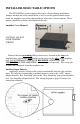
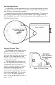
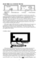
CONTROL HEAD
The control
head is designed to
be flush mounted.
Select a location
such as the dash,
the overhead
console, or a center
console. Choose a
mounting location
convenient to the
operator and away
from any air bag
deployment areas.
Be sure to choose a location that has at least two inches of depth to accommodate
the control head and cables. Consider wire routing and access to connections when
selecting location as well.
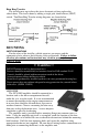
Mark the mounting hole locations and the area to be cut out using the control
head installation template provided on page 19. CAUTION: Use extreme caution
not to oversize the cutout area. The control head will only overlap this cutout
hole by 1/8" on the top and the bottom. Temporarily place the control head in the
cutout opening to verify the alignment of the unit. Remove the control head and
connect the communication cable and the two power cables. If the option jumpers
on the back of the control head have not been previously set, refer to the Installer
Selectable Options section on pages 3-6. Permanently mount the control head using
four #6 screws (not provided).
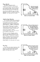
MICROPHONE BRACKET
A metal clip is provided for mounting the microphone. Choose a location
convenient to the operator and away from any air bag deployment areas. Using the
mounting clip as a template, mark the two holes to be drilled. Using a 1/8" drill bit,
drill the two mounting holes. Install the two #6 screws provided with the bracket.
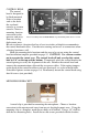
Please note that for the SS741MG-TEC the 7-position knob functions are reversed.