
Owner`s manual


Page 20 of 28 RD0169 (A) CAF730 & SS730 OWNER’S MANUAL
6.7 SUSPENSION PROCEDURES
The basic procedure for suspending CAF730s and SS
730s or a combination of both is similar.
What varies is how different pallets affect handling of the enclosures when being suspended. In
all cases, it is recommended that CAF730 enclosures be attached to an array one at a time. The
SS730 enclosures may be attached two at a time.
IMPORTANT NOTE: Always suspend all SS730s over the CAF730s.
In all cases, reverse each procedure for unrigging the array.
DANGER: Ensure each Quick Release Pin used in assembling an array is fully inserted and
engaged. Use only the 1.5 inch Quick Release Pins supplied or equal. Quick Release Pins of
different lengths or diameter will compromise the structural integrity of the enclosure and Fly-Bar
rigging system and may result in damage to the equipment, injury, or death.
CAUTION: When attaching Hinges to Hinge Tubes, use the correct holes as determined by the
CAF730 Wizard or by the user-desired angles to achieve the desired splay angle. Failure to follow
this instruction can result in poor acoustical performance.
CAUTION: To help prevent personal injury, clear all pallets as soon as they are empty from the
immediate work area.
6.7.1 CAF730s On CAF730 Pallet
1. Move a CAF730 Pallet to the rigging location.
2. Lift a CAF730 enclosure off the pallet and lay it down, positioned so its hinges are on top
and it is directly below the rigging point. The CAF730 may be laid on the floor or on a
standard road case lid at a comfortable working height.
6.7.2 SS730s on SS730 Pallet
1. Move an SS730 Pallet to the rigging location.
6.7.3 Attaching a CAF730 or SS730 to the Fly-Bar
1. Lift the Fly-Bar onto the top of the CAF730 or SS730. Orient the Fly-Bar with its corner
Hinge Tubes to the front of the loudspeakers.
2. Remove the four (SS730) or six (CAF730) Quick Release Pins from the top of the
enclosure’s Hinge Tubes.
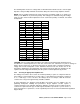
3. Slide the enclosure‘s four Hinges up into the four Hinge Tubes on the Fly-Bar. For a
CAF730, align hole 2 of the front Hinges and hole 3 of the rear Hinges with the upper hole
in each Fly-Bar Hinge Tube. For an SS730, align hole 1 of each Hinge with the upper
hole in each Fly-Bar Hinge Tube. The result will be the top of the enclosure being parallel
to the plane of the Fly-Bar when suspended.
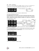
4. Attach the Hinges to the Hinge Tubes by inserting four of the Quick Release Pins.
(removed in Step 2) through both. Use ONLY the upper hole in the Fly-Bar Hinge Tubes.
5. For a CAF730, insert the remaining two Pins (removed in step 2) into the enclosure’s rear
Hinge Tubes as locking pins. See “Locking Pins” Section 6.4.5.
6. Attach the chain motors or other lifting device to the Fly-Bar, using one of the methods
detailed under “Fly-Bar Rigging Recommendations” Section 6.3.
7. Lift the array to the working height needed for the next applicable procedure in the
following sections.