
Owner`s manual


RD0169 (A) CAF730 & SS730 OWNER’S MANUAL Page 17 of 28
6.4.3 Quick Release Pins
Each CAF730 is supplied with six 1.5 inch Quick Release Pins. Four are used for attaching
enclosures together or to the Fly-Bar. Two are used as locking pins for the rear Hinges. See
“Locking Pins” Section 6.4.5. Each SS730 is supplied with four 1.5 inch Quick Release Pins used
for attaching enclosures together or to the Fly-Bar.
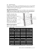
6.4.4 Hinge and Hinge Tube Holes
DANGER: Ensure each Quick Release Pin used in assembling an array is fully inserted and
engaged into the Hinge Tubes and Hinge holes. Only use the 1.5 inch Quick Release Pins
supplied or equal. Pins of different lengths or diameter will compromise the structural integrity of
the rigging system and may result in damage to the equipment, injury, or death.
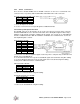
The Hinges and Hinge Tubes,
located on four corners of each
enclosure, have several holes for
inserting the Quick Release Pins
to attach enclosures together or to
the Fly-Bar. The particular holes
used will determine the splay
angles between the loudspeaker
aiming axes. The rear splays
required for these splay angles
and the Hinge and Hinge Tube
Holes to use to achieve them are
designated by theCAF730 Wizard.
NOTE: Each SS730 Hinge Tube
has only one hole for attaching the
Hinge of another enclosure. As
there is no choice of holes, it is neither labeled nor listed in the chart.
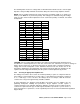
CAF730 to Fly-Bar
1
Rear Hinge Hole Rear Hinge Tube Hole Front Hinge Hole Front Hinge Tube Hole
3 Upper 2 Upper
CAF730 to CAF730
2
Front Splay Angle
Rear Hinge Hole Rear Hinge Tube Hole Front Hinge Hole
1.5° 1 A 2
3.0° 2 B 2
6.0° 3 B 2
12.0° 4 B 2
18.0° 4 B 1
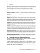
SS730 to Fly-Bar
1
Rear Hinge Hole Rear Hinge Tube Hole Front Hinge Hole Front Hinge Tube Hole
1 Upper 1 Upper
SS730 to SS730
2
Front Splay Angle
Rear Hinge Hole Front Hinge Hole
0° 2 2
CAF730 to SS730
2
Front Splay Angle Rear Hinge Hole Front Hinge Hole
-7.2° 1 2
-3.0° 2 2
0.0° 3 2
6.0° 4 2
12.0° 4 1
NOTES: 1. This positions the top surface of the enclosure so it is parallel to the plane of the CAF730 Fly-Bar.
2. The front splay angle is the between the aiming axes, not the top/bottom enclosure surfaces.