
Specifications


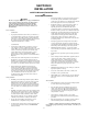


Figure 3-2. Mounting Bracket Installation.
-5-
A. Use the mounting bracket as a template
and scribe two drill positioning marks at the selected
mounting location.
CAUTION
Before drilling holes in ANY part of a vehicle,
be sure that both sides of the mounting surface
are clear of parts that could be damaged; such
as brake lines, fuel lines, electrical wiring or
other vital parts.
NOTE
If desired, the #14 thread-forming screws
may be used in place of the 1/4-20 x 3/4 hex
head screws.
B. Drill two mounting holes at the position
marks.
C. Secure the mounting bracket to the mount-
ing surface with (2 each) 1/4-20 x 3/4 hex head
screws, 1/4 split lockwashers and 1/4-20 hex nuts as
shown in figure 3-2.
3-5. CONTROL HEAD INSTALLATION.
Several control head mounting methods are
available. The mounting method used will depend on
available room, and user preference.
CAUTION
Unreliable switch activation and loss of “tactile
feedback” will result if the control head mount-
ing method allows movement. DO NOT mount
the control head on padded surfaces.
WARNING
When installing equipment inside air
bag equipped vehicles, the installer
MUST ensure that the equipment is
installed ONLY in areas recommended
by the vehicle manufacturer.
Failure to observe this warning will
reduce the effectiveness of the air bag,
damage the air bag, or potentially dam-
age or dislodge the equipment, causing
serious injury or death to you or others.
Choose a location for the control head that
allows the vehicle, controls, and microphone to be
operated safely at all times.
See figure 3-3. The supplied hinged mounting
bracket enables the control head to be mounted in a
variety of positions. Positioning the bracket above the
unit allows mounting the control head on the under-
side of the dash. Positioning the bracket below the
unit will permit mounting on any horizontal surface.
To mount the control head using the bracket, proceed
as follows:
A. Assemble a bracket to the control head
using the 6-32 x 1/4 screws and #6 lockwashers.
Assemble the other bracket to the control head/
bracket assembly using the 1/4-20 x 3/4 hex head
screws and 1/4" lockwashers as shown in figure 3-4.
NOTE
The brackets are not symmetrical. After assem-
bling the brackets to the control head, ensure
that the assembly can be properly positioned
at the intended mounting location. If proper
positioning cannot be achieved, reverse the
bracket.
B. Use the mounting bracket as a template
and scribe two drill positioning marks at the selected
mounting location.
CAUTION
Before drilling holes in ANY part of a vehicle,
be sure that both sides of the mounting sur-
face are clear of parts that could be damaged;
such as brake lines, fuel lines, electrical wiring
or other vital parts.
290A4023-03
B
NOTE:
ONLY ONE BRACKET IS SUPPLIED.
1/4-20 x 7/16"
SCREW, TYPE
TT THD. HEX
WSH.HD
BLK. OXIDE (2)
1/4" SPLIT
LOCKWASHER
SmartSiren SM
SS2000SM
MOUNTING
R
L
I
G
H
T
S
K
E
Y
P
A
D
F
E
D
E
R
A
L S
IG
N
A
L C
O
R
P
.
S
m
artsiren S
M
S
S
2000S
M
3
2
1
A
B
C
D
E
S
ig
n
a
lM
a
s
te
r
A
U
X
O
U
T
P
U
T
+
B
A
T
M
I
C
SignalM
aster
FUSE
1/4-20 x 3/4" HEX
HD. CAP SCREW (2)
OPTIONAL #14 THD.
FRM. SCREW (2) MAY
BE SUBSTITUTED
(BOTH SUPPLIED)
MOUNTING
BRACKET (1)
1/4" SPLIT
LOCKWASHER (4)
1/4-20 HEX NUT (2)