
Installation Manual

ValveWatch II Hardware Installation and Setup Manual
Page 22 of 34
CRANE
Nuclear
• The HUB assembly can be mounted in any vertical position in the 19 in cabinet. The assembly
should be mounted so that the cables from the hazardous area enter the assembly on the hazardous
entry side and are at least 2 inches from non-hazardous cables in the same cabinet. The HUB
Assembly may be installed upside down to orient the hazardous cable entry openings with the
hazardous cable location.
• Mount the HUB assembly in the 19 inch cabinet with at least 4 mounting screws (not provided in
the kit).
• If RF communications will be used for the installation, install the HUB assembly antenna
according to the next procedure section now and return to this step afterwards.
• Attach the RJ45 Ethernet connector from the ValveWatch Ethernet module to the associated
system network. The network can be a plant/platform network or a dedicated router/satellite link
for remote monitoring.
• Connector the power cord to the IEC connector on the HUB Assembly but do not plug into the
power plug at this time.
• AC input is protected with a replaceable fuse. The fuse is located under the IEC60320 C14 inlet
connector. Recommended fuse for product is a LittleFuse, 216 Series, 5x20mm, 250VAC, from 5
to 10 Amps Rating (10 amp supplied).
• The DC power supply output is protected by an 6.3 amp fuse located on the DIN rail.
Recommended fuse is a LittleFuse, 216 Series, 5x20mm, 250VAC, 6.3 Amp Rating.
• TB3-Ex is designated as the hazardous area field termination connections. From 1 to 8 valves may
be connected to the HUB assembly provided that safety barriers are provided.
• The DC voltage shall not exceed 28 Volts DC
• The DC current shall not exceed 250 milliamps AC
• All field wiring and equipment shall have at least 500 Volt isolation to ground except earth ground
terminals.
• Route the low voltage DC power supply cable(s) from the hazardous area located ValveWatch
LDAU assemblies to the ValveWatch HUB assembly in the safe area according to local cable
routing specifications or codes. Connect power supply conductors to the TB3-Ex terminals
according to J-51009ExS and local field drawings. Secure the cable with cable ties.
• It is critical that the wiring be installed correctly. There are two power supply barriers associated
with the ValveWatch system. One barrier is connected to the ValveWatch sensor modules and the
second barrier is connected to the ValveWatch communications module. Properly label the
individual wires on both LDAU and HUB side of the field cable(s).
• Plug the power cord into a local AC power outlet.
• With the power cord connected to the unit and the unit connected to the valve LDAU(s), plug the
AC power cord into the customer power plug.
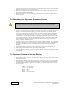
6.4 HUB Antenna Assembly Installation
This section is required only if the system is being configured in RF mode
• The antenna location for the Hub Assembly will be selected a safe area or Zone 2.
• Selection will require that the antenna be strategically located for receiving RF
communications from ValveWatch LDAU assemblies. The Antenna Assembly needs to be
mounted in an area equivalent to the environment of the Hub Assembly certification. The
LDAU’s communicating with the HUB Assembly need to be in the same general area as the
HUB Antenna. The antenna should be mounted to prevent personnel from having normal
access within a 20 cm distance from the antenna.
• The maximum distance from a HUB Assembly antenna to a LDAU antenna should not
exceed 1000 ft.
• The HUB Assembly Antenna cable should not exceed 100 ft. The antenna will need to be
placed in close proximity to the final location of the Hub Assembly.
• Before mounting any RF equipment, a trained RF surveillance engineer should verify all
LDAU and HUB Antenna Assembly mounting locations for RF propagation properties. An