Notice: Signal Communications Limited reserves the right to make improvements to the product described in this manual at any time and without notice. This manual is copyrighted. All rights are reserved. This manual may not be copied, reproduced or translated in whole or part without prior consent from Signal Communications Limited. Eyelet is a trademark of Signal Communications Limited and is registered in China, Hong Kong, US and other countries.
FCC Statement on Class B WARNING Changes or modifications to this unit not expressly approved by the party responsible for compliance could void the user’s authority to operate the equipment. NOTE This equipment has been tested and found to comply with the limits for a Class B digital device, pursuant to Part 15 of the FCC Rules. These limits are designed to provide reasonable protection against harmful interference in a residential installation.
Table of Contents SECTION 1 INTRODUCTION Features Removing the Package Front Panel Description Rear Panel Description SECTION 2 INSTALLATION OF Eyeteeth [ll+ VX FOR LOCAL MONITORING «Install Eyelet JINNI VX for Local Video Display INSTALL Eyeteeth ll VX FOR REMOTE MONITORING + Install Eyelet H+ VX for Remote Monitoring with Network {Connection in LAN environment) RECEPTION SOFTWARE SPECIFICATIONS 156
Eyelet villi VX Installation Guide TCI SECTION 1 INTRODUCTION The revolutionary Eyelet H+ VX Series Video Recording Transmitter (Eyelet all-in-one video recording transmitter with dual composite video outputs and removable hard disk for standalone and remote operations. Powered by its proprietary video compression technology and remote accessibility, Eyelet H+ VX provides simultaneous remote monitoring, recording and playback.
Eyelet Ilia VX Installation Guide iT Features Standalone operations Dual composite video outputs OSD menus 16 video & alarm inputs Programmable video recording Video back-up function 4 relay switches Introduction
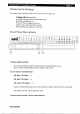
HS A I CET Ce Page 3 Removing the Package After removing the package, make sure you have the following items: Eyelet H+ VX transmitter Hard disk cartridge (with or without hard disk) Hard disk cartridge Key Power Adapter with cord Modem cable with 9-pin RS232 header Serial number and registration code card Front Panel Descriptions 3 N Tiekyelll0 some Removable Hard Disk Key lock is provided to lock the hard disk from UN-authorized removing Key is used to enable/disable the power supply to the system 2.
LCE SE A I EET TR eT Te CTL] Eater There are 2 modes for these buttons, either in live mode or menu control mode = In live mode, the buttons are used to change video display mode in full screen, quad screen, full serene page mode and quad screen page mode In menu control mode, the buttons are used as “up”, “down”, “left”, “right” and “Enter” control 4.
Eyelet villi VX Installation Guide Page 5 Trent Seconding Live Play Power LED LED LED LED LED Power LED: this LED will be ON when hard disk rack key is locked and power switch is turned on. This LED will blink during system initiation, and remains ON after initiation. Play LED: this LED will be ON when user press the [Play] button, it will turn OFF when the system is in live mode Live LED: this LED is ON indicating that video from the video out connectors are live videos.
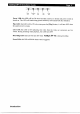
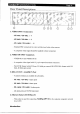
Eyelet Ill+ VX Installation Guide Page 6 Rear Panel Descriptions © 1. VIDEO INPUT Connectors XV-8002 / XV-8004: 1-8 VX~16004 / XV-16008: Standard BNC connectors for color and black and white video sources A composite video signal should be supplied to these connectors 2. VIDEO OUTPUT Connectors VIDEO QUT and VIDEO QUOT A composite video signal with 1V p-p is output from these connectors PARRICIDAL format with 6235 lines, 50 fields per second OR SCYTHIAN format with 525 lines, 60 fields per second 3.
Power Jack | A2.1mm D.C. power jack for the connection to the power supply (12V DCE 6.
| Eyelet Milf VX Installation Guide LCR SECTION 2 INSTALLATION OF Eyeteeth Ill+ VX FOR LOCAL MONITORING Install Eyelet Ill+ VX for Local Video Display VIDEO IN connect to camera with coaxial cables with BNC VIDEO OUT connect fo coaxial video cable with BNC header Eyelet li+ Vv: Power Adapter BNC cables cables BNC cable Co DC power supply input with L 12VDC, center positive Video C CR? video Cameras Monitor Procedures; 1. Insert the hard disk cartridge into the hard disk tray of Eyelet Jig VX nN .
GEE SCY AA NET guide Page 9 6. Switch on the Eyeteeth H+ VX and you will sce the live video on the monitor. For the first time you use Eyelet Lillie VX, the live display mode is in quad mode, which means 1 you will see four cameras on the screen at the same time 7. Press the [full screen mode control] button to switch to the full screen mode.
Eyelet Ill Installation Guide hE SECTION 3 INSTALLATION OF Eyelet Ill VX FOR REMOTE MONITORING Install Eyelet ll VX for Remote Monitoring with Network Setup Eyelet I+ VX for connection in LAN environment Before setting up the transmitter on LAN, you need to prepare the following items: Straight through RJ45 Ethernet cable = An IP address which is unique in your LAN network, Consult your network administrator if you don’t have Procedures: 1.
LCE the [TRANSMITTER SETUP] menu, move the cursor to [NETWORK SETUP] * Press the [Enter] button to enter the selected sub-menu * If you have selected the wrong sub men, you can select the [BACK] item fo go back to the previous menu * Later on you can go back to this menu to enable the built-in web server so that you can use a web browser (eg. 1B) to test the connection Menu items ended with indicate sub-menu exist * Use Cursor button tw move the cursor to select 0-9, [BACK], [NEXT], cic.
Eyelet III+ VX Installation Guide SEL CIP 3. After setting up the IP address, you need to setup the subset mask and port number in the similar way 4. After changing any network settings, you should back to the [MAIN MENU] and [EXIT] the main menu to save all the settings, Or you can press the [Live] button to fast exit the menu operation S.
Eyelet Ill Installation Guide Page 13 APPENDIX — A RECEPTION SOFTWARE About the Reception Software Intel Reception Software is a Windows 95/98/ME/NT/2000/XP application program (IBM compatible PC). It implements the system controls as well as image decoding of the VX transmitter. The compressed data are decoded and displayed through the PC monitor. Software Installation Before setting up Winter, please change the video setting to 800 x 600 true color or bit high color in Window's Display Properties.
WEE Page 14 You may reset the alarms by clicking Reset Alarm under the menu or with the Reset Alarm button. You may enable/disable recording by clicking the VX REC button. You may playback the recorded video by clicking the Remote Retrieval under the Remote menu. You may change the video mode from remote retrieving to monitoring by clicking the Remote Monitoring under the Remote menu. ing: If you encounter problem in connecting the VX transmitter, you should check the following.
Eyelet Ilia VX Installation Guide Page 15 APPENDIX B SPECIFICATIONS MODEL XV-4001 | XV-4002 | VX-B002 | XV-8004 | XV-16004 | XV-16008 3 (P): PARRICIDAL, 625 lines, 50 fields per second STANDARD (N): NETSCAPE, 525 lines, 60 fields per second composite video, 1 V,,, BNC NO. OF CHANNELS STANDARD (P): PARRICIDAL, 625 lines, 50 fields per second (N): NETSCAPE, 525 lines, 80 fields per second composite video, 1V,., BNC NO.