SIGLENT SVA1000X Spectrum Analyzer Service Manual SM0701X-E01A SSA3000X Service Manual 1
SIGLENT Guaranty and Declaration Copyright SIGLENT TECHNOLOGIES CO., LTD All Rights Reserved. Trademark Information SIGLENT is the registered trademark of SIGLENT TECHNOLOGIES CO., LTD Declaration SIGLENT products are protected by patent law worldwide SIGLENT reserves the right to modify or change parts of or all the specifications or pricing policies at company’s sole decision. Information in this publication replaces all previously corresponding material.
SIGLENT General Safety Summary Carefully read the following safety precautions to avoid any personal injury or damage to the instrument and any products connected to it. To avoid potential hazards, please use the instrument as specified. Use Proper AC Power Line Only the power cord designed for the instrument and authorized for its use by the local country should be used. Ground the Instrument The instrument is grounded through the protective earth conductor of the power line.
SIGLENT Safety Terms and Symbols Terms on the product. These terms may appear on the product: DANGER Indicates direct injuries or hazards may occur. WARNING Indicates potential injuries or hazards that may occur. CAUTION Indicates potential damage to the instrument or other property that may occur. Symbols on the product.
SIGLENT Contents Guaranty and Declaration ................................................................................................. 2 General Safety Summary .................................................................................................... 3 Safety Terms and Symbols .................................................................................................. 4 General Features.....................................................................................................
SIGLENT General Features General Features Siglent’s SVA1000X family of spectrum analyzers offer a frequency range of 9 kHz to 1.5 GHz. With their light weight, small size, and friendly user interface, the SVA1000X’s present a bright easy-to-read display, powerful and reliable automatic measurements, and plenty of impressive features. Applications are many, but include research and development, education, production, maintenance, and many more. Table 1-1General features Model SVA1015X SPAN 9 kHz~1.
SIGLENT Prepare Information Before initiating performance verification or any adjustments, it is recommended to follow these procedures. The following topics are discussed in this chapter. How to perform functional checks How to operate four standard interface tests How to use the self-calibration routine How to recall factory Default settings For more detailed information about analyzers operation, please refer to the SVA1000X User Manual.
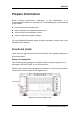
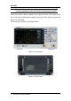
SIGLENT Note: To avoid electric shock, make sure that the instrument is correctly grounded to the earth before connecting AC power. Press the power-on button located at the lower left corner of the front panel and some keys will illuminate for about 6 seconds. Then, the boot screen will appear on the display. The front panel is shown in the figure below.
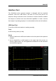
SIGLENT Interface Test The SVA1000X series spectrum analyzer is designed with four standard interfaces: USB Host, USB Device, LAN and a 3.5 mm mono jack for an earphone. Being connected to other instruments via these interfaces enables the analyzer to achieve even more enhanced capabilities. In order to ensure the analyzer is operating properly, it is recommended to first test the interfaces. USB Host Test To test if the USB Host interface is working normally. Tools: ● USB memory device (U disk) Steps: 1.
SIGLENT USB Device Test To test if the USB Device interface works normally. Tools: ● A computer with USB interface that is compatible with running National Instruments NI-MAX software ● A standard USB cable (Type A-B) ● NI-MAX software Steps: 1. Download and install National Instruments NI MAX software by following the installation instructions provided by National Instruments. 2. Connect the analyzer USB Device port and the computer using an USB cable. 3. Run NI MAX software.
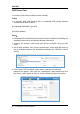
SIGLENT LAN Port Test Use to test the LAN interface functionality. Tools: ● A computer with functional LAN interface and DHCP activated. ● A standard LAN cable Steps: 1. Connect the spectrum analyzer and the computer using a LAN cable via LAN interface. 2. Press System -> Interface ->LAN, Set the IP Config to DHCP, as the figure below shows. The analyzer will set the IP Address and Subnet Mask and Gateway automatically in this network. Write down the displayed IP address. It will be used in later steps.
SIGLENT 4. Select Manual Entry of LAN instrument, select Next, and enter the IP address as shown. Click Finish to establish the connection: NOTE: Leave the LAN Device Name BLANK or the connection will fail. 4.
SIGLENT 5. Right-click on the product and select Open NI-VISA Test Panel: 6. Click “Input/Output” option button and click “Query” option button. If everything is correct, you will see the Read operation information returned as shown below. NOTE: The *IDN? command (known as the Identification Query) should return the instrument manufacturer, instrument model, serial number, and other identification information.
SIGLENT Performance Verification Test This chapter explains testing the spectrum analyzer in order to verify performance specifications. For accurate test results, please let the test equipment and the analyzer warm up 30 minutes before testing. Here is the required equipment: Table 3-1 Test equipment Equipment Specification Qty.
SIGLENT Absolute Amplitude accuracy Test Specification Preamp off ±0.4 dB, input signal -20 dBm Preamp on ±0.5 dB, input signal -40 dBm 20 °C to 30 °C, fc = 50 MHz, RBW = 1 kHz, VBW = 1 kHz, peak detector, attenuation = 20 dB Absolute amplitude accuracy Power Meter (NRP-Z91) USB USB PC BNC-BNC Ref IN Ref OUT RF Generator (SMB 100A) SVA1000X TG OUT RF OUT RF IN N-SMA N-SMA N-SMA Power divider Figure 3-1 Absolute amplitude accuracy connections Steps: 1.
SIGLENT Record: Preamp off Frequency 50 MHz Preamp on Frequency 50 MHz 16 P1 (Power Meter) P2 (Spectrum Analyzer) P1- P2 P1 (Power Meter) P2 (Spectrum Analyzer) P1- P2 SVA1000X Service Manual
SIGLENT Frequency Response Test Specification Preamp off ±0.8 dB ±0.4 dB, typ. Preamp on ±0.9 dB ±0.5 dB, typ. 20 °C to 30 °C , attenuation = 20 dB, reference frequency 50 MHz Power Meter (NRP-Z91) USB PC BNC-BNC Ref IN Ref OUT RF Generator (SMB 100A) SVA1000X TG OUT RF OUT RF IN N-SMA N-SMA N-SMA Power divider Figure 3-2 Frequency response connections Steps: 1. Connect the spectrum analyzer, signal generator and power meter as figure 3-2 shows 2.
SIGLENT ERROR = A2 – P2 8. Frequency response = |GLOBAL ERROR - SYSTEM ERROR|, compare the calculated result with the specification 9. Enable the preamplifier and set the output amplitude of the signal generator to -40dBm. Repeat steps 3 to 8 and record the results.
SIGLENT Display Average Noise Level (DANL) Test Specification Frequency RBW=10 Hz 100 kHz ~1 MHz -91 dBm, -97 dBm (typ.) 1 MHz~10 MHz -114 dBm, -120 dBm (typ.) Preamp Off 10 MHz~1 GHz -118 dBm, -124 dBm (typ.) 1 GHz~1.5 GHz -111 dBm, -117 dBm (typ.) 100 kHz ~1 MHz -110 dBm, -118 dBm (typ.) 1 MHz~10 MHz -137 dBm, -142 dBm (typ.) Preamp On 10 MHz~1 GHz -140 dBm, -146 dBm (typ.) 1 GHz~1.5 GHz -132 dBm, -138 dBm (typ.
SIGLENT Off Preamp On 20 5.005 MHz 50.005 MHz 500.005 MHz 1.500000 GHz 500.5 kHz 5.005 MHz 50.005 MHz 500.005 MHz 1.500000 GHz -114 dBm, -120 dBm (typ.) -118 dBm, -124 dBm (typ.) -118 dBm, -124 dBm (typ.) -111 dBm, -117 dBm (typ.) -110 dBm, -118 dBm (typ.) -137 dBm, -142 dBm (typ.) -140 dBm, -146 dBm (typ.) -140 dBm, -146 dBm (typ.) -132 dBm, -138 dBm (typ.
SIGLENT Phase Noise Test Specification <-95 dBc/Hz @10 kHz offset, <-99 dBc/Hz (typ.) Phase noise <-96 dBc/Hz @100 kHz offset,<-98 dBc/Hz (typ.) <-115 dBc/Hz @1 MHz offset, <-120 dBc/Hz (typ.) 20 °C to 30 °C , attenuation = 0 dB, fc = 1 GHz BNC-BNC Ref IN Ref OUT RF Generator (SMB 100A) SVA1000X RF IN TG OUT RF OUT N-SMA Figure 3-4 Phase noise verification connections Step: 1. Connect the signal generator and spectrum analyzer as figure 3-4 shows 2.
SIGLENT TOI Test Specification IIP3 +8 dBm fc≥50 MHz, two -20 dBm tones at input mixer spaced by 100 kHz, attenuation = 0 dB, preamp off, 20 °C to 30 °C BNC-BNC Ref OUT BNC-BNC Ref IN RF Generator (SMB 100A) Ref OUT Ref IN RF Generator (SMB 100A) RF OUT SVA1000X RF OUT TG OUT RF IN N-SMA N-SMA N-SMA Power divider Figure 3-5 TOI verification connections Step 1. Connect double signal generators to a power divider and the output of the divider to RF IN port of spectrum analyzer 2.
SIGLENT Frequency Accuracy Test Specification Reference frequency Initial calibration accuracy 10.000000 MHz < 1 ppm Channel A BNC-BNC AWG Generator (SDG 1050) Ref IN OCXO Ref OUT Channel B SVA1000X TG OUT RF IN Figure 3-6 Connecting test instruments for frequency accuracy Steps: 1. Connect ref out port of the spectrum analyzer to the channel A of the SDG1050, which is referenced by an OCXO 2. Set the SDG1050 to frequency counter mode, and set the frequency ref to 10.000000 MHz 3.
SIGLENT 1dB Gain Compression Test Specification Power Meter (NRP-Z91) 1dB Gain Compression > -5 dBm 20 °C to 30 °C, fc = 50 MHz, attenuation = 0 dB, preamp off Ref OUT SIGNAL Generator (SDG1000) RF OUT BNC-SMA N-SMA Ref IN Power divider RF Generator (SMB 100A) RF OUT N-SMA (a) Ref IN Ref OUT SIGNAL Generator (SDG1000) SVA1000X TG OUT RF OUT RF IN BNC-SMA N-SMA Ref IN RF Generator (SMB 100A) RF OUT Power divider N-SMA (b) Figure 3-7 connecting test instruments for 1dB Gain Compression Tes
SIGLENT the amplitude to -5 dBm. 3. Enable the output of the signal generator and disable the output of the RF generator. Observe the measurement value of the power meter. Adjust the output amplitude of the signal generator until the reading of the power meter becomes -25 dBm. 4. Enable the output of the RF generator and disable the output of signal generator. Observe the measurement value of the power meter.
SIGLENT Second Harmonic Distortion Test Specification Power Meter (NRP-Z91) Second Harmonic Distortion Test < -65 dBc 20 °C to 30 °C, fc = 50MHz, attenuation = 0 dB, preamp off, mixer level = -30 dBm Ref OUT RF Generator (SMB 100A) RF OUT N-SMA Low Pass Filter N-SMA (a) BNC-BNC Ref IN Ref OUT RF Generator (SMB 100A) SVA1000X N-SMA RF IN TG OUT RF OUT Low Pass Filter N-SMA (b) Figure 3-8 connecting test instruments for Second Harmonic Distortion Test Steps: 1.
SIGLENT 4. Configure the spectrum analyzer: a) Set the center frequency to 50 MHz. b) Set the span to 10 kHz. d) Set the reference level to -30 dBm. e) Set the input attenuation to 0 dB. f) Set the resolution bandwidth to 300 Hz. g) Set the video bandwidth to 10 Hz. h) Set the sweep time to auto and the auto sweep time to accuracy. 5. Press Peak to find the maximum value P1. Then, Set the center frequency to 100 MHz, Press Peak to find the maximum value P2.
SIGLENT Input Attenuation Error Test Specification Power Meter (NRP-Z91) Input Attenuation Error Test <±0.5 dB 20 °C to 30 °C, fc= 50 MHz, preamp off, mixer level= -30 dBm Ref OUT RF Generator (SMB 100A) RF OUT N-N (a) BNC-BNC Ref OUT Ref IN RF Generator (SMB 100A) RF OUT SVA1000X TG OUT RF IN N-N (b) Figure 3-9 Connecting test instruments for Input Attenuation Error Test Steps: 1. Connect the RF generator and power meter as figure 3-9(a) shows 2.
SIGLENT 4. Connect the RF generator and spectrum analyzer as figure 3-2(b) shows 5. Set the output frequency of the RF generator to 50 MHz and the amplitude to P-10. 6. Configure the spectrum analyzer: a) Set the center frequency to 50 MHz. b) Set the span to 10 kHz. c) Set the reference level to 0 dBm. d) Set the input attenuation to 20 dB. e) Set the resolution bandwidth to 1 kHz and the video bandwidth to 10 Hz. f) Set the sweep time to auto and the auto sweep time to accuracy. 7.
SIGLENT Tracking Generator (TG) Test Specification Frequency range Output level Output flatness 5 MHz ~1.5 GHz -20 dBm ~ 0 dBm +/-3 dB SVA1000X TG OUT RF IN N-N Figure 3-10 Connecting test instruments for TG Output Steps: 1. Connect the RF IN port and TG OUT port by an N-N cable as figure 3-10 shows 2. Configure the spectrum analyzer: (a) Open the TG mode (b) Set the span to full span (c) Set the Ref level to 0 dB (d) Set the RBW and VBW to Auto 3.
SIGLENT Assembly Procedures This chapter describes how to remove the major modules from the SVA1000X spectrum analyzer. To install the removed modules or replace new modules, please follow the corresponding operating steps in reverse order. This chapter includes the following topics: Security Consideration which describes security information needed to consider while operating. List of Modules in which the modules to remove are listed.
SIGLENT List of Modules The following removable modules are listed in the order of performing disassembly procedures.
SIGLENT Disassembly Procedures This section describes how to remove and install the modules listed above in the spectrum analyzer in detail. Complete disassembly will be best achieved through the following operating steps. Removing the Rear Panel Figure 4-1 Removing the Rear Panel Screws Removal steps: 1. Remove each rear panel screws as shown in figures above. 2. Press the place of the front panel as the arrows point in the first figure and remove the rear panel from the machine.
SIGLENT Removing the Front Panel Figure 4-2 Removing the front panel Removal steps: 1. Place the analyzer face down on a soft surface such as an anti-static mat. 2. Remove the six screws located on the rear panel. In this same position, remove the four screws located on the standing legs. 3. Lift the rear panel up and off carefully. To install the rear panel, please follow these same steps in reverse order.
SIGLENT Removing the Rear Metal Cover BNC nuts Figure 4-3 Removing the rear metal cover Removal steps: 1. Place the analyzer down on a soft surface such as an anti-static mat. 2. Remove the screws located on the rear metal cover. 3. Remove three nuts from the Back BNC terminal. 4. Disconnect the power cable and fan cable connected to the main board module from the power supply module. 5.
SIGLENT Removing the Main Board, Channel Board Figure 4-4 View of front panel subassembly with main board Removal steps: 1. Place the analyzer back side down on a soft surface such as an anti-static mat. 2. Remove the screws located on the metal shelf and each board. 3. Remove the RF board, TG board, Digital board from the metal shelf.
SIGLENT To install the front panel, please perform these steps in reverse order. Removing the LCD, Keyboard Figure 4-5 Removing the LCD and keyboard Removal steps: 1. Remove the silicone keypad. 2. Remove the four screws located on the edge of the display module. 3. Remove the six screws located on the channel board. 4. Remove the seven screws located on the keyboard. 5. Disconnect the cable that connected the keyboard and the channel board. 6. Separate the modules carefully.
SIGLENT Contact SIGLENT SIGLENT Technologies Co., Ltd Address:3/F, building NO.4, Antongda Industrial Zone, 3rd Liuxian Road, Bao’an District, Shenzhen, P.R.China Tel:0086-755-3688 7876 E-mail: sales@siglent.com http://www.siglent.com SIGLENT Technologies America, Inc Address: 6557 Cochran Rd Solon, Ohio 44139 E-mail: info@siglent.com http://www.siglentamerica.com SIGLENT Technologies EuropeGmbH Address: Liebigstrasse 2-20, Gebaeude 14, 22113 Hamburg Germany E-Mail: info-eu@siglent.com http://www.