
Programming Guide


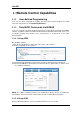


Table Of Contents
- 1. Programming Overview
- 2. SCPI Overview
- 3. System Commands
- 3.1 IEEE Common Commands
- 3.1.1 Identification Query (*IDN)
- 3.1.2 Reset (*RST)
- 3.1.3 Clear Status (*CLS)
- 3.1.4 Standard Event Status Enable (*ESE)
- 3.1.5 Standard Event Status Register Query (*ESR)
- 3.1.6 Operation Complete Query (*OPC)
- 3.1.7 Service Request Enable (*SRE)
- 3.1.8 Status Byte Query (*STB)
- 3.1.9 Wait-to-Continue (*WAI)
- 3.1.10 Self Test Query (*TST)
- 3.2 System Subsystem
- 3.2.1 System Time (:SYSTem:TIME)
- 3.2.2 System Date (:SYSTem:DATE)
- 3.2.3 IP Address (:SYSTem:COMMunicate:LAN:IPADdress)
- 3.2.4 Gateway (:SYSTem:COMMunicate:LAN:GATeway)
- 3.2.5 Subnet Mask (:SYSTem:COMMunicate:LAN:SMASk)
- 3.2.6 IP Config (:SYSTem:COMMunicate:LAN:TYPE)
- 3.2.7 Language (:SYSTem:LANGuage)
- 3.2.8 Power On Type (:SYSTem:PON:TYPE)
- 3.2.9 System Preset (:SYSTem:PRESet)
- 3.2.10 System Restart (:SYSTem:RESTart)
- 3.2.11 Preset Type (:SYSTem:PRESet:TYPE)
- 3.2.12 Factory ReSet (:SYSTem:FDEFault)
- 3.2.13 Enable Option (:SYSTem:LKEY)
- 3.2.14 Installed Options Query (:SYSTem:OPTions?)
- 3.2.15 Power Off (:SYSTem:POWer:OFF)
- 3.2.16 System Info (:SYSTem:CONFigure:SYSTem?)
- 3.3 Instrument Subsystem
- 3.4 Initiate Subsystem
- 3.5 Sense Subsystem
- 3.5.1 Frequency Subsection
- 3.5.1.1 Center Frequency ([:SENSe]:FREQuency:CENTer)
- 3.5.1.2 Start Frequency ([:SENSe]:FREQuency:STARt)
- 3.5.1.3 Stop Frequency ([:SENSe]:FREQuency:STOP)
- 3.5.1.4 Center Frequency Step ([:SENSe]:FREQuency:CENTer:STEP[:INCRement])
- 3.5.1.5 Center Frequency Step Mode ([:SENSe]:FREQuency:CENTer:STEP:AUTO)
- 3.5.1.6 Sets CF→Step ([:SENSe]:FREQuency:CENTer:SET:STEP)
- 3.5.1.7 Frequency Span ([:SENSe]:FREQuency:SPAN)
- 3.5.1.8 Full Span ([:SENSe]:FREQuency:SPAN:FULL)
- 3.5.1.9 Zero Span ([:SENSe]:FREQuency:SPAN:ZERO)
- 3.5.1.10 Last Span ([:SENSe]:FREQuency:SPAN:PREVious)
- 3.5.1.11 Zoom In ([:SENSe]:FREQuency:SPAN:HALF)
- 3.5.1.12 Zoom Out ([:SENSe]:FREQuency:SPAN:DOUBle)
- 3.5.2 Auto Tune Subsection
- 3.5.3 Amplitude Subsection
- 3.5.3.1 Reference Level (:DISPlay:WINDow:TRACe:Y[:SCALe]:RLEVel)
- 3.5.3.2 Input Attenuator ([:SENSe]:POWer[:RF]:ATTenuation)
- 3.5.3.3 Attenuator Auto Mode ([:SENSe]:POWer[:RF]:ATTenuation:AUTO)
- 3.5.3.4 Preamp on-off ([:SENSe]:POWer[:RF]:GAIN[:STATe])
- 3.5.3.5 Amplitude OffSets (:DISPlay:WINDow:TRACe:Y:SCALe:RLEVel:OFFSet )
- 3.5.3.6 Amplitude Units (:UNIT:POWer)
- 3.5.3.7 Scale Type (:DISPlay:WINDow:TRACe:Y[:SCALe]:SPACing)
- 3.5.3.8 Scale/Div (:DISPlay:WINDow:TRACe:Y[:SCALe]:PDIVision)
- 3.5.3.9 Correction Off ([:SENSe]:CORRection:OFF)
- 3.5.3.10 Correction Apply State ([:SENSe]:CORRection:CSET:ALL[:STATe])
- 3.5.3.11 Sets Correction X State Off ([:SENSe]:CORRection:CSET[1]|2|3|4:OFF)
- 3.5.3.12 Set Correction Data ([:SENSe]:CORRection:CSET[1]|2|3|4:DATA)
- 3.5.3.13 Input Impedance ([:SENSe]:CORRection:IMPedance[:INPut][:MAGNitude])
- 3.5.4 Bandwidth Subsection
- 3.5.4.1 Resolution Bandwidth ([:SENSe]:BWIDth[:RESolution])
- 3.5.4.2 Resolution Bandwidth Auto Mode ([:SENSe]:BWIDth[:RESolution]:AUTO)
- 3.5.4.3 Video Bandwidth ([:SENSe]:BWIDth:VIDeo)
- 3.5.4.4 Auto Video Bandwidth State ([:SENSe]:BWIDth:VIDeo:AUTO)
- 3.5.4.5 Video to Resolution Bandwidth Ratio ([:SENSe]:BWIDth:VIDeo:RATio)
- 3.5.4.6 Auto Video to Resolution Bandwidth Ratio State ([:SENSe]:BWIDth:VIDeo:RATio:CONfig?)
- 3.5.4.7 Filter Type ([:SENSe]:FILTer:TYPE)
- 3.5.5 Trace Subsection
- 3.5.6 Detector Subsection
- 3.5.7 Average Subsection
- 3.5.8 Sweep Subsection
- 3.5.9 Display Subsection
- 3.5.1 Frequency Subsection
- 3.6 Calculate Subsystem
- 3.6.1 Marker Subsection
- 3.6.1.1 Marker On/Off (:CALCulate:MARKer[1]|2|3|4|5|6|7|8:STATe)
- 3.6.1.2 Marker All Off (:CALCulate:MARKer:AOFF)
- 3.6.1.3 Marker Mode (:CALCulate:MARKer[1]|2|3|4|5|6|7|8:MODE)
- 3.6.1.4 Marker to Trace (:CALCulate:MARKer[1]|2|3|4|5|6|7|8:TRACe)
- 3.6.1.5 Marker Relative To (:CALCulate:MARKer[1]|2|3|4|5|6|7|8:RELative:TO)
- 3.6.1.6 Marker X Value (:CALCulate:MARKer[1]|2|3|4|5|6|7|8:X)
- 3.6.1.7 Query Marker Y Value (:CALCulate:MARKer[1]|2|3|4|5|6|7|8:Y?)
- 3.6.1.8 Marker Table (:CALCulate:MARKer:TABLe)
- 3.6.1.9 Marker to Start Frequency (:CALCulate:MARKer[1]|2|3|4|5|6|7|8[:SET]:START)
- 3.6.1.10 Marker to Stop Frequency (:CALCulate:MARKer[1]|2|3|4|5|6|7|8[:SET]:STOP)
- 3.6.1.11 Marker to Center Frequency (:CALCulate:MARKer[1]|2|3|4|5|6|7|8[:SET]:CENTer)
- 3.6.1.12 Marker to Center Frequency Step (:CALCulate:MARKer[1]|2|3|4|5|6|7|8[:SET]:STEP)
- 3.6.1.13 Marker to Reference Level (:CALCulate:MARKer[1]|2|3|4|5|6|7|8[:SET]:RLEVel)
- 3.6.1.14 Marker Delta to Span (:CALCulate:MARKer[1]|2|3|4|5|6|7|8:DELTa[:SET]:SPAN)
- 3.6.1.15 Marker Delta to Center Frequency (:CALCulate:MARKer[1]|2|3|4|5|6|7|8:DELTa[:SET]:CENTer)
- 3.6.1.16 Peak Search Type (:CALCulate:MARKer:PEAK:SEARch:MODE)
- 3.6.1.17 Peak Threshold (:CALCulate:MARKer:PEAK:THReshold)
- 3.6.1.18 Peak Excursion (:CALCulate:MARKer:PEAK:EXCursion)
- 3.6.1.19 Peak Table (:CALCulate:MARKer:PEAK:TABLe)
- 3.6.1.20 Continuous Peaking Marker (:CALCulate:MARKer[1]|2|3|4|5|6|7|8:CPEak[:STATe])
- 3.6.1.21 Peak Search (:CALCulate:MARKer[1]|2|3|4|5|6|7|8:MAXimum)
- 3.6.1.22 Next Peak Search (:CALCulate:MARKer[1]|2|3|4|5|6|7|8:MAXimum:NEXT)
- 3.6.1.23 Marker Peak Left Search (:CALCulate:MARKer[1]|2|3|4|5|6|7|8:MAXimum:LEFT)
- 3.6.1.24 Marker Peak Right Search (:CALCulate:MARKer[1]|2|3|4|5|6|7|8:MAXimum:RIGHt)
- 3.6.1.25 Peak to Peak Search (:CALCulate:MARKer[1]|2|3|4|5|6|7|8:PTPeak)
- 3.6.1.26 Marker Function (:CALCulate:MARKer[1]|2|3|4|5|6|7|8:FUNCtion)
- 3.6.1.27 Frequency Counter (:CALCulate:MARKer:FCOunt[:STATe])
- 3.6.1.28 Query Frequency Counter (:CALCulate:MARKer:FCOunt:X?)
- 3.6.1.29 N dB Bandwidth Result (:CALCulate:MARKer:BANDwidth:RESult?)
- 3.6.1.30 N dB Bandwidth Reference Value (:CALCulate:MARKer[1]|2|3|4|5|6|7|8:BANDwidth:NDB?)
- 3.6.1.31 Marker X-Axis Read Out (:CALCulate:MARKer[1]|2|3|4|5|6|7|8:X:READout)
- 3.6.2 Limit Subsection
- 3.6.2.1 Limit Test Start (:CALCulate:LLINe:TEST:STARt)
- 3.6.2.2 Limit Test Stop (:CALCulate:LLINe:TEST:STOP)
- 3.6.2.3 Gets Limit Test State (:CALCulate:LLINe:TEST:STATe?)
- 3.6.2.4 Limit Line State (:CALCulate:LLINe[1]|2:STATe)
- 3.6.2.5 Limit Type (:CALCulate:LLINe[1]|2:TYPE)
- 3.6.2.6 Limit Mode (:CALCulate:LLINe[1]|2:MODE)
- 3.6.2.7 Limit Line Y-axis Value (:CALCulate:LLINe[1]|2:Y)
- 3.6.2.8 Define Limit Points Data (:CALCulate:LLINe[1]|2:DATA)
- 3.6.2.9 Add Limit Point Data (:CALCulate:LLINe[1]|2:DATA)
- 3.6.2.10 Delete Assigned Limit Point (:CALCulate:LLINe[1]|2:DELete)
- 3.6.2.11 Delete All Limit Points (:CALCulate:LLINe:ALL:DELete)
- 3.6.2.12 Limit X-axis Unit (:CALCulate:LLINe:CONTrol:DOMain)
- 3.6.2.13 Limit Beep State (:CALCulate:LLINe:CONTrol:BEEP)
- 3.6.2.14 Query Limits Result (:CALCulate:LLINe:FAIL?)
- 3.6.2.15 Limit Fail to Stop (:CALCulate:LLINe:FAIL:STOP)
- 3.6.1 Marker Subsection
- 3.7 Measurement Subsystem
- 3.7.1 ACPR Subsection
- 3.7.1.1 Main Channel ([:SENSe]:ACPRatio:BWIDth:INTegration)
- 3.7.1.2 Adjacent Channel Bandwidth ([:SENSe]:ACPRatio:OFFSet:BWIDth[:INTegration])
- 3.7.1.3 Channel Space ([:SENSe]:ACPRatio:OFFSet[:FREQuency])
- 3.7.1.4 Query Main Channel Power (:MEASure:ACPRatio:MAIN?)
- 3.7.1.5 Query Lower Adjacent Channel Power (:MEASure:ACPRatio:LOWer:POWer?)
- 3.7.1.6 Query Lower Adjacent Channel Power Ratio (:MEASure:ACPRatio:LOWer?)
- 3.7.1.7 Query Upper Adjacent Channel Power (:MEASure:ACPRatio:UPPer:POWer?)
- 3.7.1.8 Query Upper Adjacent Channel Power Ratio (:MEASure:ACPRatio:UPPer?)
- 3.7.2 CHP Subsection
- 3.7.2.1 Integration BW ([:SENSe]:CHPower:BWIDth:INTegration)
- 3.7.2.2 Channel Span ([:SENSe]:CHPower:FREQuency:SPAN:POWer)
- 3.7.2.3 Query Channel Power and Power Spectral Density (:MEASure:CHPower?)
- 3.7.2.4 Query Channel Power (:MEASure:CHPower:CHPower?)
- 3.7.2.5 Query Power Spectral Density (:MEASure:CHPower:DENSity?)
- 3.7.3 OBW Subsection
- 3.7.3.1 Select the Method of OBW ([:SENSe]:OBWidth:METHod)
- 3.7.3.2 Set Percentage(%) Method of OBW ([:SENSe]:OBWidth:PERCent)
- 3.7.3.3 Set dBc Method of OBW ([:SENSe]:OBWidth:XDB)
- 3.7.3.4 Query OBW and Centroid (:MEASure:OBWidth?)
- 3.7.3.5 Query OBW (:MEASure:OBWidth:OBWidth?)
- 3.7.3.6 Query OBW Centroid (:MEASure:OBWidth:CENTroid?)
- 3.7.3.7 Query Transmit Frequency Error (:MEASure:OBWidth:OBWidth:FERRor?)
- 3.7.4 SubsectionT-power(T-Power)
- 3.7.5 Spectrum Monitor(SPECtrogram)
- 3.7.6 Third-order Intercept Point(TOI)
- 3.7.1 ACPR Subsection
- 3.8 Trigger Subsystem
- 3.9 TG Subsystem
- 3.9.1 TG On-off (:OUTPut[:STATe])
- 3.9.2 TG Level (:SOURce:POWer[:LEVel][:IMMediate][:AMPLitude])
- 3.9.3 TG Level OffSets (:SOURce:CORRection:OFFSet )
- 3.9.4 TG Normalize on-off (:CALCulate:NTData[:STATe])
- 3.9.5 TG Normalize Reference Level (:DISPlay:WINDow:TRACe:Y[:SCALe]:NRLevel)
- 3.9.6 TG Normalize Reference Position (:DISPlay:WINDow:TRACe:Y[:SCALe]:NRPosition)
- 3.9.7 TG Normalize Reference Trace on-off (:DISPlay:WINDow:NTTRace[:STATe])
- 3.10 Demod Subsystem
- 3.11 Memory Subsystem
- 3.1 IEEE Common Commands
- 4. Programming Examples

SIGLENT
SVA1000X Programming Guide 3
1.Programming Overview
The Siglent SVA1000X series spectrum analyzers features LAN, USB Device, and SIGLENT
GPIB_USB module interfaces. By using a computer with these interfaces, and a suitable
programming language (and/or NI-VISA software), users can remotely control the analyzer
based on SCPI (Standard Commands for Programmable Instruments) command set,
Labview and IVI (Interchangeable Virtual Instrument), to interoperate with other
programmable instruments.
This chapter introduces how to build communication between the spectrum analyzer and a
controller computer with these interfaces.
1.1 Remotely Operating the Analyzer
The analyzer provides both the USB and LAN connection which allows you to set up a
remote operation environment with a controller computer. A controller computer could be a
personal computer (PC) or a minicomputer. Some intelligent instruments also function as
controllers.
1.1.1 USB: Connecting the Analyzer via the USB Device
port
Refer to the following steps to finish the connection via USB-Device:
1. Install NI-VISA on your PC for USB-TMC driver.
2. Connect the analyzer USB Device port to a PC with a USB A-B cable.
Figure 1-1 USB Device
3. Switch on the analyzer
The analyzer will be detected automatically as a new USB hardware.
1.1.2 LAN: Connecting the Analyzer via the LAN port
Refer to the following steps to finish the connection via LAN:
1. Install NI-VISA on your PC for VXI driver. Or without NI-VISA, using socket or telnet
in your PC’s Operating System.
2. Connect the analyzer to PC or the local area network with a LAN cable