
User Manual
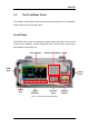
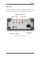
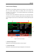
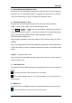

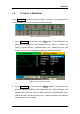
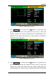

Table Of Contents
- General Safety Summary
- Introduction of SDG2000X
- Quick Start
- Front Panel Operations
- To Set Sine Waveform
- To Set Square Waveform
- To Set Ramp Waveform
- To Set Pulse Waveform
- To Set Noise Waveform
- To Set DC Waveform
- To Set Arbitrary Waveform
- To Set Harmonic Function
- To Set Modulation Function
- To Set Sweep Function
- To Set Burst Function
- To Store and Recall
- To Set Utility Function
- Examples
- Example 1: Generate a Sine Waveform
- Example 2: Generate a Square Waveform
- Example 3: Generate a Ramp Waveform
- Example 4: Generate a Pulse Waveform
- Example 5: Generate a Noise
- Example 6: Generate a DC Waveform
- Example7: Generate a Linear Sweep Waveform
- Example 8: Generate a Burst Waveform
- Example 9: Generate an AM Modulation Waveform
- Example 10: Generate a FM Modulation Waveform
- Example 11: Generate a PM Modulation Waveform
- Example 12: Generate a FSK Modulation Waveform
- Example 13: Generate an ASK Modulation Waveform
- Example 14: Generate a PSK Modulation Waveform
- Example 15: Generate a PWM Modulation Waveform
- Example 16: Generate a DSB-AM Modulation Waveform
- Troubleshooting
- Service and Support
- Appendix

SIGLENT
6 SDG2000X User Manual
3. Basic Waveform Parameters Area
Shows the current waveform‘s parameters of each channel. Press Parameter
and select the corresponding softkey to highlight the parameter to configure.
Then use number keys or knob to change the parameter value.
4. Channel Parameters Area
Displays the load and output settings of the currently selected channel.
Load ----Value of the output load, as selected by the user.
Press Utility → Output → Load, then use the softkeys, number keys or knob to
change the parameter value; or continue pressing the corresponding output
key for two second to switch between High Impedance and 50Ω.
High Impedance: display HiZ.
Load: display impedance value (the default is 50Ω and the range is 50Ω to
100kΩ).
Note: This setting does not actually change the instrument‘s output impedance
of 50Ω but rather is used to maintain amplitude accuracy into different load
values.
Output ----Channel output state.
After pressing corresponding channel output control port, the current channel
can be turned on/off.
5. LAN Status Icon
SDG2000X will show different prompt messages based on the current network
status.
This mark indicates LAN connection is successful.
This mark indicates there is no LAN connection or LAN connection is
unsuccessful.
6. Mode Icon
SDG2000X will show different prompt messages based on the current mode.
This mark indicates current mode is Phase-locked.