
User Manual
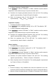
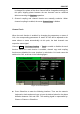
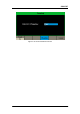

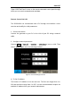


Table Of Contents
- General Safety Summary
- Introduction of SDG2000X
- Quick Start
- Front Panel Operations
- To Set Sine Waveform
- To Set Square Waveform
- To Set Ramp Waveform
- To Set Pulse Waveform
- To Set Noise Waveform
- To Set DC Waveform
- To Set Arbitrary Waveform
- To Set Harmonic Function
- To Set Modulation Function
- To Set Sweep Function
- To Set Burst Function
- To Store and Recall
- To Set Utility Function
- Examples
- Example 1: Generate a Sine Waveform
- Example 2: Generate a Square Waveform
- Example 3: Generate a Ramp Waveform
- Example 4: Generate a Pulse Waveform
- Example 5: Generate a Noise
- Example 6: Generate a DC Waveform
- Example7: Generate a Linear Sweep Waveform
- Example 8: Generate a Burst Waveform
- Example 9: Generate an AM Modulation Waveform
- Example 10: Generate a FM Modulation Waveform
- Example 11: Generate a PM Modulation Waveform
- Example 12: Generate a FSK Modulation Waveform
- Example 13: Generate an ASK Modulation Waveform
- Example 14: Generate a PSK Modulation Waveform
- Example 15: Generate a PWM Modulation Waveform
- Example 16: Generate a DSB-AM Modulation Waveform
- Troubleshooting
- Service and Support
- Appendix

SIGLENT
112 SDG2000X User Manual
is changed, the phase of the other channel will be changed accordingly. At
this point, aligning phase between the two channels can be achieved
without executing the Eqphase operation.
3. Channel coupling and channel function are mutually exclusive. When
channel coupling is enabled, the menu Channel Copy is hidden.
Channel Track
When the track function is enabled, by changing the parameters or states of
CH1, the corresponding parameters or states of CH2 will be adjusted to the
same values or states automatically. At this point, the dual channels can
output the same signal.
Choose Utility → CH Copy Coupling → Track to enable or disable the track
function. When the track function is enabled, channel copy and coupling
functions are disabled; the user interface is switched to CH1 and cannot be
switched to CH2, as shown in the following figure.
Figure 2-70 Track Interface
Press PhaseDev to enter the following interface. Then use the numeric
keyboard or knob and arrow keys to input the desired value for the phase
deviation between CH1 and CH2. The resulting signal is represented by:
Phase
CH2
-Phase
CH1
=PhaseDev.