
User Manual
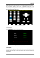
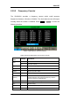
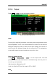
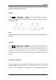


Table Of Contents
- General Safety Summary
- Introduction of SDG2000X
- Quick Start
- Front Panel Operations
- To Set Sine Waveform
- To Set Square Waveform
- To Set Ramp Waveform
- To Set Pulse Waveform
- To Set Noise Waveform
- To Set DC Waveform
- To Set Arbitrary Waveform
- To Set Harmonic Function
- To Set Modulation Function
- To Set Sweep Function
- To Set Burst Function
- To Store and Recall
- To Set Utility Function
- Examples
- Example 1: Generate a Sine Waveform
- Example 2: Generate a Square Waveform
- Example 3: Generate a Ramp Waveform
- Example 4: Generate a Pulse Waveform
- Example 5: Generate a Noise
- Example 6: Generate a DC Waveform
- Example7: Generate a Linear Sweep Waveform
- Example 8: Generate a Burst Waveform
- Example 9: Generate an AM Modulation Waveform
- Example 10: Generate a FM Modulation Waveform
- Example 11: Generate a PM Modulation Waveform
- Example 12: Generate a FSK Modulation Waveform
- Example 13: Generate an ASK Modulation Waveform
- Example 14: Generate a PSK Modulation Waveform
- Example 15: Generate a PWM Modulation Waveform
- Example 16: Generate a DSB-AM Modulation Waveform
- Troubleshooting
- Service and Support
- Appendix

SIGLENT
110 SDG2000X User Manual
Channel coupling or track function and channel copy function are mutually
exclusive. When channel coupling or track function is enabled, the menu
Channel Copy is hidden.
Channel Coupling
The SDG2000X supports frequency, amplitude and phase coupling. Users can
set the frequency deviation/ratio, amplitude deviation/ratio or phase deviation
/ratio of the two channels. When coupling is enabled, CH1 and CH2 can be
modified simultaneously. When the frequency, amplitude or phase of one
channel (as the reference) is changed, the corresponding parameter of the
other channel will be changed automatically and always keeps the specified
frequency deviation/ratio, amplitude deviation/ratio or phase deviation /ratio
relative to the base channel.
Press Utility → CH Copy Coupling → Channel Coupling, to enter the following
interface.
Figure 2-69 Channel Coupling Interface
Frequency Coupling
1. To Enable Frequency Coupling Function
Press FreqCoup to turn frequency coupling ―On‖ or ―Off‖. The default is ―Off‖.