
User Manual
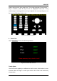
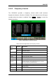
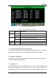
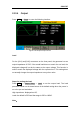


Table Of Contents
- General Safety Summary
- Introduction of SDG2000X
- Quick Start
- Front Panel Operations
- To Set Sine Waveform
- To Set Square Waveform
- To Set Ramp Waveform
- To Set Pulse Waveform
- To Set Noise Waveform
- To Set DC Waveform
- To Set Arbitrary Waveform
- To Set Harmonic Function
- To Set Modulation Function
- To Set Sweep Function
- To Set Burst Function
- To Store and Recall
- To Set Utility Function
- Examples
- Example 1: Generate a Sine Waveform
- Example 2: Generate a Square Waveform
- Example 3: Generate a Ramp Waveform
- Example 4: Generate a Pulse Waveform
- Example 5: Generate a Noise
- Example 6: Generate a DC Waveform
- Example7: Generate a Linear Sweep Waveform
- Example 8: Generate a Burst Waveform
- Example 9: Generate an AM Modulation Waveform
- Example 10: Generate a FM Modulation Waveform
- Example 11: Generate a PM Modulation Waveform
- Example 12: Generate a FSK Modulation Waveform
- Example 13: Generate an ASK Modulation Waveform
- Example 14: Generate a PSK Modulation Waveform
- Example 15: Generate a PWM Modulation Waveform
- Example 16: Generate a DSB-AM Modulation Waveform
- Troubleshooting
- Service and Support
- Appendix

SIGLENT
104 SDG2000X User Manual
Figure 2-65 Counter Setup Interface
Table 2-36 Menu Explanations of Setup
Function
Menu
Settings
Explanation
Mode
DC
Set the coupling mode to DC
AC
Set the coupling mode to AC
HFR
On
Open the high frequency rejection filter.
Off
Close the high frequency rejection filter.
Default
Set the frequency counter settings to default.
Done
Save the current settings and return to the previous menu.
1. To Select the Parameters to be measured
The frequency counter on the SDG2000X can measure parameters including
frequency, period, duty, positive pulse width and negative pulse width.
2. Reference Frequency
System will calculate the deviation between the measured frequency and the
reference frequency automatically.
3. Trigger Level
Sets the trigger level of the measurement system. The system triggers and
obtains the measurement readings when the input signal reaches the
specified trigger level. The default is 0V and the available range is from -3V to