
SIGRC19EPARFB-Manual

c) Keep sliding the wire in until the short top leg exits the slot
in the stabilizer.
d) Hold the nylon tailwheel bearing in place on the bottom of
the fuselage. Mark the mounting hole locations and then drill
1/16" dia. pilot holes in the fuselage. Then screw the bearing in
place with the two M3 x 12mm Screws provided.
e) Leave the wheel collar that is between the bearing and the
coil in the wire loose for now.
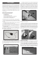
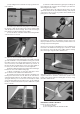
❑ 17) Now it's time to install the rudder permanently.
a) Note that the bottom leading edge of the rudder is already
grooved and drilled to accept the tailwheel steering wire. Trial fit
the rudder onto the wire and up against the back of the fin. Be
sure to have the top of the rudder even with the top of the fin - at
this point the wire should be able to move up or down slightly as
necessary, since the wheel collar has not been tightened.
b) Take the rudder back off the wire and insert the CA Hinges
back into the slots in the rudder leading edge.
c) Mix up a small batch of epoxy glue and apply it in the
groove and hole in the rudder for the tailwheel wire.
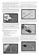
d) Carefully insert the front side of the three CA Hinges into
the hinge slots in the back of the fin, while at the same time in-
serting the tailwheel wire into the rudder. Watch for any excess
epoxy glue that may ooze out of the wire slot and wipe it off with
a rag soaked in rubbing alcohol. When you’ve got the rudder all
the way on, double check that the top of the rudder lines up with
the top of the fin.
e) Finish the rudder installation by gluing the CA Hinges in
place with Thin CA, using the same techniques you did for the
aileron hinges back in Step 2.
f) After all the glue is dry, adjust the wheel collar to sit snug
against the bottom of the nylon tailwheel bearing. The purpose
of the wheel collar is to keep any loads from the tailwheel from
putting stress on the rudder.
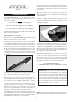
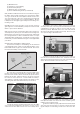
❑ 18) Hinge the elevator to the stabilizer, using the same tech-
niques you did for the ailerons back in Step 2 of this manual. Let
the hinges dry before flexing them.
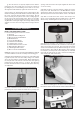
❑ 19) Look closely and you will find three holes pre-drilled near
the bottom of the rudder for mounting a nylon control horn. Install
the control horn on the left side of the rudder, with the retaining
plate on the right, using three M2 x 16mm Screws.
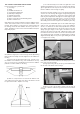
❑ 20) There are three holes pre-drilled in the elevator for mounting
a nylon control horn. Screw the control horn in position on the
bottom of the elevator, with the retaining plate on the top, using
three M2 x 16mm Screws.
ELEVATOR & RUDDER CONTROLS
For this section you will need:
(1) Fuselage Assembly
(2) 35.5" long Wire Pushrods with M2 Hex Nut
9