
SIGRC19EPARFB-Manual
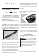
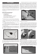
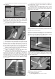

b) Now carefully insert the exposed portion of the three
hinges into the trailing edge of the wing. You will find it easiest to
slide the hinges into the slots at angle, one hinge at a time, instead
of trying to push it straight onto all the hinges at once.
c) Adjust the aileron so that the tip of the aileron is flush with
the wing tip. The ailerons should be tight against the pins in the
hinges to minimize the gap between the wing and the aileron. The
aileron is now in the proper position for permanently gluing them
in place with thin CA glue.
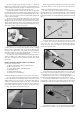
d) Flex the aileron down and hold it in this position. Remove
the pins from one hinge and then carefully apply 3-4 drops of Thin
CA glue directly onto the hinge in the gap. You will notice that the
glue is quickly wicked into the slot as it penetrates both the wood
and the hinge. We suggest using a fine tipped applicator on the
glue bottle to better control the flow of glue.
e) Turn the part over and glue the other side of the hinge.
Continue this process until you have glued both sides of all the
hinges! Keep a rag handy to wipe off any excess Thin CA glue.
(If you get some glue smears on the plastic covering, don't worry
about them right now. Once all the hinging is done, you can clean
the smears off the covering with CA Debonder).
f) Let the glue dry 10-15 minutes before flexing the hinges.
At first you might notice a little stiffness in the joint. This will go
away after the hinges have been flexed back and forth a couple
dozen times.
INSTALL AILERON CONTROL HORNS & PUSHRODS
From the kit contents locate:
(2) Nylon Control Horns (without retaining plates)
(6) M2 x 16 mm Screws
(2) 7” long Pushrod Wires with M2 Hex Nut
(2) Metal R/C Clevis
(2) Pushrod Snap Keepers
(2) small pieces of Fuel Tubing
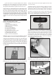
❑ 3) Mount the Nylon Control Horns on the bottom of the ailerons.
a) Look closely and you will see three holes pre-drilled in the
bottom of the ailerons for mounting the nylon control horns. Screw
a M2 x 14mm screw into each hole. Screw them all the way in,
and then screw them all the way back out. This creates threads
in the hardwood block in the ailerons. With the screws removed,
put one drop of thin CA ngue into each hole. Let dry before pro-
ceeding. This hardens the threads for long life.
b) When dry, mount the control horn in position on the bottom
of the aileron with the screws. Do the same for the other aileron.
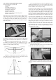
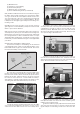
❑ 4) Next assemble and install the aileron pushrods.
a) Slide a short piece of Fuel Tubing onto the small end of
the Metal R/C Clevis. Screw the Hex Nut on the Aileron Pushrod
Wire all the way up to the end of the threads. Then screw the
metal clevis halfway onto the threaded end of the Aileron Pushrod
Wire.
b) Clip the metal clevis into the last hole in the nylon control
horn. Lay the other end of the pushrod wire over the outer hole
in the servo arm. Use a felt tip pen to mark the wire where it
crosses the hole. Use a pair of pliers to put a sharp 90-degree
bend in the wire at the mark.
c) Insert the bent end of the pushrod into the servo arm, from
the top. Note: You will most likely need to use a 1/16” dia. drill to
open the hole in the servo arm to accept the pushrod wire.
d) Mark and cut off the excess end of the pushrod wire, leav-
ing 1/8” of wire protruding below the bottom of the servo arm.
e) Clip a Nylon Snap Keeper in place on the servo end of the
pushrod wire. Snap the free end of the keeper up and over the
protruding end of the pushrod wire, underneath the servo arm.
f) Check that the aileron servo is in neutral position and adjust
the metal clevis as needed to get the aileron in neutral position.
6