
SIGRC19EPARFB-Manual

12
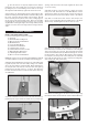
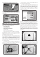
with a 7/32" dia. drill. Install four M4 Blind Nuts in the holes, on
the back side of the firewall. Put a couple drops of glue on the
flanges of the blind nuts to secure them to the plywood. Be careful
not to get any of the glue in the threads.
❑ 28) If you have not already re-attached the X mount plate to the
back of your motor, do so now. Then use (4) M4 x 16mm Socket-
Head Mounting Bolts and Lock Washers to bolt your motor in
place on the plywood motor mount box.
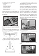
❑ 29) A long piece of balsa triangle stock provided to reinforce
the motor mount. Measure, cut and glue pieces of triangle stock
in all the corner joints inside the motor mount box.
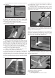
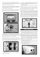
❑ 30) Two hook-&-loop (Velcro®) straps are provided to hold your
lipo battery pack in place inside the fuselage. Feed the straps
through the slots in one side of the plywood battery tray, and then
up through the other side. Put a couple small dabs of 5-minute
epoxy to glue the straps to the plywood battery tray.
Optional: In addition to the two straps, it is a good idea to use
hook-&-loop tape (not furnished) on the bottom of your battery
pack and on the top surface of the plywood battery tray, to make
sure the battery pack will not move around during aerobatics.
❑ 31) Install your ESC
a) Solder appropriate battery connectors (not supplied) to the
battery leads of your ESC.
b) Decide on a good location to mount the ESC. The most
likely place in the KADET SENIORITA is in the top of the nose,
above the plywood battery tray. Use a plastic cinch strap to secure
it to the airplane structure.
c) Now route the ESC’s servo wire back to the receiver and
plug it in.
d) Connect the ESC's motor wires to the motor. Operate the
motor and check the direction of rotation. Always do this without
a propeller attached! If you need to reverse the rotation, refer to
the instructions that came with the motor and ESC.
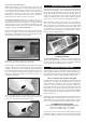
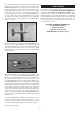
SAFETY ISSUE: We strongly recommend the use of an “arming
switch” (not supplied) for your motor installation. With an arming
switch you can install your battery pack in the airplane and hook
up the wires without danger of the motor starting. The arming
switch keeps the electricity away from the motor until you “arm” it
when you are ready to takeoff. The most common arming
switches are a simple external plug that puts a break in the posi-
tive battery lead to the motor, such as the Maxx Products Arming
Switch shown below. There are also arming switches built into
some of the advanced ESCs now on the market.
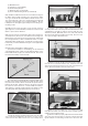
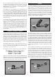
❑ 32) Mount the cowling on the fuselage with the four M3 x 9mm
Screws provided. Notice that the holes for the four cowl mounting
screws are already pre-drilled in the cowling - two on each side.
a) First test fit the cowling on the fuselage. As you pass it
over the motor, make sure all the wires are out of the way. Care-
fully adjust the exact position of the cowling. Make sure you have
adequate clearance between the front of the cowl and the back
of the propeller, and that the prop shaft is centered in the hole.
Use low tack tape to hold the cowling in place for the next step.
b) Use a 5/64" or #45 bit to drill a pilot hole for the top left
cowl mounting screw. Center the drill in the hole in the cowling
and drill into the fuselage side. Install an M3 x 10mm screw in
the pilot hole - do not over-tighten the screw.
c) Recheck the position of the cowling and make any adjust-
ments needed to get it back in position.
d) Now drill another pilot hole for the upper screw on the other
side of the cowling. Install the screw.
e) Repeat this process to install the two bottom cowl mount-
ing screws. Remove all the tape.
MOUNT THE COWLING