
SIGRC19EPARFB-Manual

tighten the M2 Hex Nut up against the back of the clevis
❑ 25) Locate the pushrod exit hole for the elevator inside the rear
of the fuselage and repeat step 24) in its entirety to install the el-
evator pushrod.
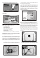
For this section you will the Fuselage and:
(1) Fiberglass Cowling
(4) M3 x 9mm Screws
(1) Balsa Triangle Stock
(4) M4 x 16mm Socket-Head Bolts
(4) M4 Split-Ring Lock Washers
(4) M4 Blind Nuts
(2) Hook-&-Loop (Velcro®) Straps
(1) Electric Motor, ESC, Prop, Lipo Battery (not furnished)
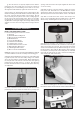
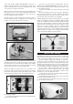
❑ 26) NOTE: The mounting of the electric motor in the KADET
SENIORITA assumes that your motor has a typical "X" or "cross"
mounting plate on the back of the motor.
Also note that the firewall portion of the laser-cut plywood motor
mount is adjustable fore and aft to accommodate different length
motors. In this step we will adjust the motor mount for your par-
ticular electric motor. For the KADET SENIORITA we need a total
distance from the back of the plywood motor mount box to the
motor’s thrust washer to end up exactly 4.2”. This distance allows
the cowling to fit properly.
a) Assemble your motor according to the manufacturer's in-
structions. Then carefully measure the distance from the back of
the mounting plate to the front of the thrust washer *.
* The “thrust washer” is the part of the prop adaptor where the
back of the propeller will be located.
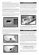
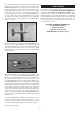
b) Subtract the measurement taken in the previous step a)
from 4.2”. The result is the distance you need to locate the front
of the firewall from the back of the plywood motor mount box.
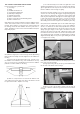
Carefully measure and mark the distance determined from the
back edge of the motor mount box towards the front. Make the
measurement along the top edge of the plywood side of the motor
mount box, as shown here.
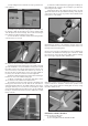
c) Carefully align the front face of the firewall with your marks.
Make sure you end up with the firewall straight and square in the
box. If it is not, recheck your marks and adjust as necessary.
d) Tack glue the firewall in place. Recheck once more to
make sure that the front of the firewall is at the correct distance
from the back of the motor mount box. That distance plus the
length of your motor must equal 4.2”. When satisfied it is correct,
glue the firewall securely to the rest of the motor mount box.
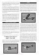
❑ 27 a) Note the short lines that are laser cut on the front of the
firewall to indicate the thrust line for the motor. Use a sharp pencil
to extend the lines at the 45 degree positions out to the edges of
the firewall.
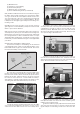
b) Center your X mount plate over the 45 degree lines. Once
you are sure it is properly located, mark the mounting holes with
a pencil. Set the X mount aside and drill out the mounting holes
11
ELECTRIC MOTOR INSTALLATION