
SIGRC19EPARFB-Manual

(2) Metal RC Clevis
(2) small pieces of Fuel Tubing
(2) Pushrod Snap Keepers
(1) Radio Receiver (not furnished)
(2) Servos with Mounting Screws (not furnished)
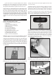
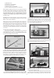
❑ 21) Install the rudder and elevator servos inside the fuselage in
the built-in plywood radio mounting tray. Note that the rudder
servo goes on the left side of the airplane, and the elevator servo
goes on the right side. (The servo opening in the front right side
of the tray is for the throttle servo in a glow installation.) Be sure
to drill pilot holes through the plywood tray for the mounting servo
mounting screws.
❑ 22) Mount your receiver in a place of your choosing. If using a
glow engine it is recommended that you wrap the receiver in foam
rubber to protect it from vibrations.
❑ 23) If you are using a receiver battery pack (some electric pow-
ered setups don't), mount your on/off switch in the fuselage side.
Note that there are precut holes in the fuselage sides, underneath
the covering material, for either a standard size switch or a super
switch with built-in charging plug. Cut away the covering over the
hole that fits your switch and mount using the screw supplied with
your switch.
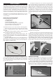
❑ 24) Assemble and install the rudder pushrod.
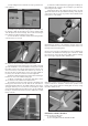
a) First slide a small piece of Fuel Tubing onto the small end
of the Metal R/C Clevis. Next screw the Hex Nut that is on the
Pushrod Wire all the way up to the end of the threads. Then screw
the metal clevis halfway onto the threads.
b) Locate the pre-cut pushrod exit hole for the rudder on the
left side of the fuselage alongside the fin. Slide the plain end of
the pushrod wire into the exit hole and inside the pushrod sleeve
built into the fuselage. Slide it in until you can clip the clevis into
the outer hole of the control horn. Lock the rudder in neutral po-
sition with tape, or with two small scrap balsa wood sticks or dow-
els held together with small rubber bands (as shown here).
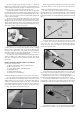
c) Inside the fuselage, hold the pushrod wire over the rudder
servo output arm and mark the wire where it crosses over the
outer hole in the arm. Make sure the servo is in neutral position.
d) Unclip the clevis from the rudder control horn so that you
can now pull as much of the wire pushrod forward into the radio
compartment as possible, to make is easier to finish the servo
end of the pushrod. Mark and cut the servo end of the pushrod
wire1/4" past the mark you made in the last step. Then use a pli-
ers to put a 90-degree bend in the wire.
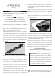
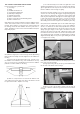
e) With the pushrod still disconnected from the rudder, re-
move the servo control arm from the servo. Install the servo arm
and a nylon pushrod snap keeper on the end of the pushrod, as
shown. Then re-install the servo arm on the servo.
f) Make sure that the rudder servo is in neutral position and
then adjust the metal clevis at the tail end as needed to get the
rudder in perfect neutral position.
g) After the rudder is properly adjusted, insure that the metal
clevis can’t open up and come loose from the control horn by slid-
ing the small piece of fuel tubing over the arms of the clevis. Also
10