
Manual


Maintenance
19 07.02GB
5. Thumb down take down lever 5 (seeFig. 12 on
page 16).
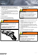
6. Insert recoil spring guide 22 and recoil spring
23 into slide 24 (see Fig. 19).
7. From the front, slip assembled slide onto the
guide rails of frame 7.
8. Draw back slide 24 to the rear stop. Thumb up
slide catch lever 8 to arrest slide in its open
position (see Fig. 11 on page 16).
9. Flip up the take down lever 5 counter-
clockwise.
10.Actuate slide catch lever 8; slide 24 is impelled
forward.
Note:
• The pistol is unloaded and decocked.
8.5 Verification of functions
Note:
• Verification of functions must be conducted on
the assembled pistol:
– to identify causes of malfunction,
– after completion of repairs,
– and after each cleaning and assembly of
the pistol.
Procedure:
1. Make sure that the magazine is removed and
the pistol unloaded (see section “Unloading
the pistol” on page 10).
2. Check the elasticity of the recoil spring 23 and
the smoothness of the slide 24 (no jamming).
– Draw back slide 24 to the stop and allow it
to fly forward.
– Check that slide 24 is impelled forward with
sufficient energy and that it locks up.
– Repeat the verification test.
3. Check the trigger mechanism.
– With hammer 14 decocked, pull trigger 13
through.
– Check that hammer 14 cocks and that at
the end of trigger travel, it strikes firmly
forward.
4. Check trigger travel and trigger interruption.
– With hammer 14 decocked and trigger 13
pulled through, draw back slide 24 to the
stop and release it.
Fig. 18
CAUTION!
Slide, recoil spring guide and recoil spring
are only connected loosely with each other
May lead to injuries and damage to the pistol
• When recoil spring 23 is inserted into slide
24, it becomes preloaded. If the recoil spring
guide 22 is not carefully installed in slide, it
can fly out together with the recoil spring and
injure you or someone in your vicinity.
Fig. 19
1.
2.
2124
2.
1.
23 2224