
User Manual

12
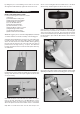
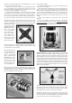
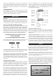
❑ 35) Mount the cowling on the fuselage with the four M3 x 10mm
Screws provided. Notice that the holes for the four cowl mounting
screws are already pre-drilled in the cowling - two on each side.
a) First test fit the cowling on the fuselage. As you pass it over
the motor, make sure all the wires are out of the way. Carefully
adjust the exact position of the cowling. Make sure you have ad-
equate clearance between the front of the cowl and the back of
the propeller, and that the prop shaft is centered in the hole. Use
low tack tape to hold the cowling in place for the next step.
b) Use a 5/64" or #45 bit to drill a pilot hole for the top left cowl
mounting screw. Center the drill in the hole in the cowling and
drill into the fuselage side. Install an M3 x 10mm screw in the pilot
hole - do not over-tighten the screw.
c) Recheck the position of the cowling and make any adjust-
ments needed to get it back in position.
d) Now drill another pilot hole for the upper screw on the other
side of the cowling. Install the screw.
e) Repeat this process to install the two bottom cowl mounting
screws. Remove all the tape.
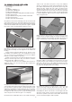
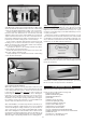
❑ 36) COOLING IS IMPORTANT!
With a fully cowled motor, it is very important to make sure your
power system is getting proper cooling. Air flowing into the front
of the cowling must have a place to exit the cowl. In fact it’s best
to have more air exit area
than inlet area to create a positive air
flow through the cowling - an actual suction effect - drawing the
heated air out of the cowling so that more cool air can come in.
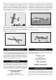
This positive air flow keeps your motor running cool. We recom-
mend that you make a simple opening at the bottom rear edge of
the cowling as shown in the next photo, to provide additional air
exit area. The exact dimensions are not critical.
Note: A Dremel® Tool, or similar rotary hand-tool, with an assort-
ment of bits is without a doubt the best tool to use for making
cutout in the fiberglass cowling. However, if you do not have ac-
cess to such a tool, you can cut the opening with a drill, a hobby
knife, and a sanding block. First first drill a series of almost touch-
ing 1/8” holes inside the pattern lines; then use the knife to cut
through the connecting material between each hole; and finally
finish the edges of the opening with the file or a sanding block.
Additional Cooling Options:
You may find after test flying that your
ESC or battery pack need additional cooling. We have not found
that to be necessary with our prototype 4-STAR 64, but it could
happen in some cases with different motors, props, etc. If you
need more cooling air flowing over the ESC and battery, here are
a couple good options.
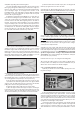
Option #1) To get more air flowing into the fuselage, you can
open another hole in the firewall. Near the bottom of the firewall
you will find an oval shape that is only partially cut through. It is
easy to finish the cut and remove the oval, which will allow air to
flow directly over the ESC under the battery tray.
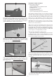
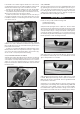
Option #2) If you need more air flowing out of the fuselage,
make an air exit hole in the bottom rear of the fuselage, back near
the tail, as shown here.
❑ 37) Mount a suitable propeller (not furnished) on your motor.
Be sure to balance the propeller before installation.
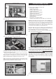
Skip this section if your using an electric power setup
For this section you will need the Fuselage and:
(2) Nylon Engine Mounts
(4) M4 x 30mm Mounting Bolts
(4) M4 Flat Metal Washers
(1) Fuel Tank
(1) Rubber Stopper Assembly
(1) Fuel Pick-Up Weight (clunk)
(1) Fuel Line Tubing for inside tank
(1) Plywood Fuel Tank Support
(1) Balsa Block for Fuel Tank Stop
(1) Nylon Throttle Pushrod Tube
(1) 19.75" long Wire Pushrod with M2 Hex Nut
(1) Metal Pushrod Keeper with Set Screw and Hex Nuts
(1) Metal RC Clevis
(1) small piece of Fuel Tubing for clevis
(2) Hook-&-Loop (Velcro®) Straps
GLOW POWER SYSTEM