
User Manual

the front. Do this along side each of the adjustment slots on both
sides of the box (four marks total).
c) After you have all four slots marked, carefully align the front
face of the firewall to line up with the marks. Make sure you end
up with the firewall straight and square in the box. If it is not,
recheck your marks and adjust as necessary.
d) Tack glue the firewall in place. Recheck once more to make
sure that the front of the firewall is at the correct distance from the
back of the motor mount box. That distance plus the length of
your motor must equal 5-9/16” (5.5625”). When satisfied it is cor-
rect, glue the firewall securely to the rest of the motor mount box.
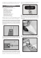
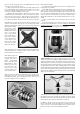
❑ 29) Remove the X mount plate from the back of your motor and
center it on the firewall. Once you are sure it is properly located,
mark the mounting holes with a pencil. Remove the X mount and
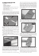
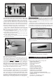
❑ 30) Locate the piece of balsa triangle stock provided. Measure,
cut and install pieces of triangle stock to reinforce all the corner
joints inside the motor mount box.
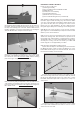
❑ 32) If you have not already re-attached the X mount plate to the
back of your motor, do so now. Then use (4) M4 x 16mm Socket-
Head Mounting Bolts and Lock Washers to bolt your motor in
place on the plywood motor mount box.
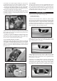
❑ 33) Install your ESC
a) Solder appropriate battery connectors (not supplied) to the
battery leads of your ESC.
b) The ESC will sit underneath the battery tray behind the fire-
wall. If you are using a thinner ESC you can slide the ESC into
the bay via the opening in the firewall below the electric motor box.
If you are using a thick ESC with a heat sink you will need to cut
open the front slot in the battery tray. Secure the ESC in place
with double-sided tape or Velcro® tape (neither of these are pro-
vided).
c) Now route the ESC’s servo wire back to the receiver and
plug it in.
d) Connect the ESC's motor wires to the motor. Operate the
motor and check the direction of rotation. Always do this without
a propeller attached! If you need to reverse the rotation, refer to
the instructions that came with the motor and ESC.
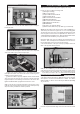
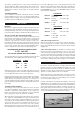
SAFETY ISSUE: We strongly recommend the use of an “arming
switch” for your motor installation. With an arming switch you can
install your battery pack in the airplane and hook up the wires
without danger of the motor starting. The arming switch keeps
the electricity away from the motor until you “arm” it when you are
ready to takeoff. The most common arming switches are a simple
external plug that puts a break in the positive battery lead to the
motor, such as the Maxx Products Arming Switch shown below.
There are also arming switches built into some of the advanced
ESCs now on the market.
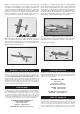
❑ 34) Two hook-&-loop (Velcro®) straps are provided to hold your
lipo battery pack in place inside the fuselage. Feed the straps
through the slots in one side of the plywood battery tray, and then
up through the other side, as shown in the next photo.
In addition to the two straps, it is a good idea to use hook-&-loop
tape (not furnished) on both the bottom of your battery pack and
on the top surface of the plywood battery tray, to make sure the
battery pack will not move around during aerobatics.
11
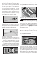
❑ 31) Bolt the plywood
motor mount box to the
fuselage with M4 x
20mm Socket-Head
Bolts and M4 Flat
Metal Washers. Note
that two access holes
have been cut in the
bottom corners of the
firewall to allow access
for your hex wrench.
drill out the mounting
holes with a 7/32"
dia. drill. Install four
M4 Blind Nuts in the
holes, on the back
side of the firewall.
Put a couple drops of
glue on the flanges
of the blind nuts to
secure them to the
plywood. Be careful
not to get any of the
glue in the threads.