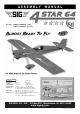
KIT NO.: SIGRC73EGARFR - (red) SIGRC73EGARFY - (yellow) SPECIFICATIONS: Wing Span: Wing Area: Length: Flying Weight: Wing Loading: Radio Req.: Glow Power: Electric Power: 64 in. (1625 mm) 847 sq.in. (54.6 dm2) 57 in. (1447 mm) 7 - 8.25 lbs. (3175 - 3742 g) 19 - 22 oz./sq.ft. (58 - 68 g/dm2) 4-Channel with 5 Standard Servos (glow) 4-Channel with 4 Standard Servos (electric) 2-Stroke .60 - .75 cu.in. (10.0 - 12.3 cc) 4-Stroke .60 - .90 cu.in. (10.0 - 14.
Whatever brand engine you choose, take the time to carefully break it in according to the manufacturer's instructions. A good running, reliable engine is a minimum requirement for the enjoyment of this or any R/C model aircraft. ❑ PROPELLER FOR GLOW Refer to the engine manufacturer’s instructions for recommendations on proper propeller size for their engine. In our experience, most 2-stroke .60-.75 glow engines will fly the 4-STAR 64 very nicely with a 12x8 or 13-6 prop.
tions. 1) Switch to a lower power setup under the rating of your BEC; or 2) disable the BEC and install a normal receiver battery pack to run the radio full time; 3) install an aftermarket BEC that is properly rated for your setup. Covering Iron & Trim Seal Tool Masking Tape Paper Towels Alcohol and/or Acetone For Epoxy Clean-up ❑ 4 cell 5000mah or 6 cell 4000mah LIPO BATTERY PACK You can fly your 4-STAR 64 with a 4 cell (4S1P) or 6 cell (6S1P) Lipo pack.
❑ (5) ❑ (5) ❑ (4) ❑ (2) ❑ (2) ❑ (1) shirt, to prevent scratching the covering as you work. After covering your iron, the next step is to set the iron to the correct temperature. This is critical for achieving a good result! The iron should be set to about 220OF - 250OF (104OC - 121OC) as measured on the bottom of the iron using a thermometer.
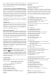
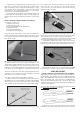
servo mounting screws. Use the screws supplied with your radio system to mount the servo in place on the servo mount. Repeat this procedure to mount the servo in the opposite wing panel. WING ASSEMBLY The wings are designed as a 2-piece system, with separate right and left wing panels joined by an aluminum tube wing joiner and a hardwood locating pin at the rear. Due to the high strength of the wing joiner tube, the wing panels do not need to be permanently glued together.
e) Turn the part over and glue the other side of the hinge. Continue this process until you have glued both sides of all the hinges! Keep a rag handy to wipe off any excess Thin CA glue. (If you get some glue smears on the plastic covering, don't worry about them right now. Once all the hinging is done, you can clean the smears off the covering with CA Debonder). f) Let the glue dry 10-15 minutes before flexing the hinges. At first you might notice a little stiffness in the joint.
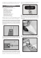
by sliding the piece of Fuel Tubing over the arms of the clevis. Also tighten the M2 Hex Nut up against the back of the clevis. wheel. Leave a small gap between it and the wheel, so the wheel will turn freely, and then tighten the wheel collar set screw. FUSELAGE ASSEMBLY INSTALL THE MAIN LANDING GEAR Locate the following parts from the kit contents: (1) Fuselage (2) Aluminum Main Landing Gear (3) M4 x 20mm Socket-Head Bolts (3) M4 Split-Ring Lock Washers (2) 3-1/4" dia. Main Wheels (2) 4mm dia.
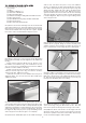
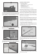
TAIL SURFACE & TAILWHEEL INSTALLATION For the following steps you will need: (1) Fuselage (1) Wing (1) Stabilizer & Elevator set (1) Vertical Fin & Rudder Set (2) M6.5 Nylon Wing Bolts (1) Tailwheel assembly, including Wheel and Wheel Collars (2) M3 x 12mm Screws (1) Nylon Rudder Steering Clasp with Bolt and Hex Nut (2) Nylon Control Horns (6) M2 x 14mm Sheet Metal Screws aside for now. Test fit the fin in place on top of the stabilizer.
ELEVATOR & RUDDER CONTROLS For this section you will need: (1) Fuselage Assembly (2) 35.5" long Wire Pushrods with M2 Hex Nut (2) Metal RC Clevis (2) small pieces of Fuel Tubing (2) Pushrod Snap Keepers (1) Radio Receiver (not furnished) (2) Servos with Mounting Screws (not furnished) ❑ 22) Install the rudder and elevator servos inside the fuselage in the built-in plywood radio mounting tray. Note that the rudder servo goes on the right side of the airplane, and the elevator servo goes on the left side.
ELECTRIC POWER SYSTEM Skip this section if your using a glow engine power setup For this section you will the Fuselage and: (1) Fiberglass Cowling (4) M3 x 10mm Screws (1) Plywood Electric Motor Mount (1) Balsa Triangle Stock (4) M4 x 20mm Socket-Head Bolts (4) M4 Flat Metal Washers (4) M4 x 16mm Socket-Head Bolts (4) M4 Split-Ring Lock Washers (4) M4 Blind Nuts (2) Hook-&-Loop (Velcro®) Straps (1) Electric Motor, ESC, Prop, Lipo Battery (not furnished) d) Cut the wire ¼” past the mark and then put a 90-de
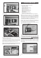
❑ 33) Install your ESC a) Solder appropriate battery connectors (not supplied) to the battery leads of your ESC. b) The ESC will sit underneath the battery tray behind the firewall. If you are using a thinner ESC you can slide the ESC into the bay via the opening in the firewall below the electric motor box. If you are using a thick ESC with a heat sink you will need to cut open the front slot in the battery tray.
Additional Cooling Options: You may find after test flying that your ESC or battery pack need additional cooling. We have not found that to be necessary with our prototype 4-STAR 64, but it could happen in some cases with different motors, props, etc. If you need more cooling air flowing over the ESC and battery, here are a couple good options. Option #1) To get more air flowing into the fuselage, you can open another hole in the firewall.
f) Glue the balsa block fuel tank stop in place on the plywood tank tray, up against the rear end of the tank. ❑ 38) Start by putting the Fuel Tank together. a) Locate the Rubber Stopper Assembly. There are three nylon tubes going through the rubber stopper. Orient the stopper so that one of the tubes is towards the top and then bend that tube up at a 45-degree angle. Do not apply heat to the tube - it will bend without heat.
to the throttle servo and the engine’s throttle arm. In most cases you will want the pushrod to run right alongside the engine mount and fuel tank, and then angle over to the throttle servo arm. d) Drill a hole through the firewall for the nylon pushrod tube to pass through. Be careful not to drill a hole in your fuel tank! e) Install the metal pushrod keeper in the throttle servo arm, with one hex nut above the arm, and one below.
good bond. Carefully place the canopy onto the fuselage and check it’s alignment. With a wet paper towel, wipe off any excess glue that seeps out from the canopy. Once this is clean use some masking tape to hold the canopy in place on the plane while the glue dries. posite effect: Moving it closer to center will decrease throw, and away from center will increase throw. Work with a combination of the two to achieve the closest or exact control throws listed.
With the control movements set at the “low rate” measurements the airplane should exhibit smooth, predictable control. Try a few loops and rolls. Inverted flight is easy, requiring a little down elevator for level flight. The 4-STAR 64 also performs nice inside and outside loops, snap rolls, Immelmanns, stall turns, Cuban eights, and spins. Of course it is not a pattern aircraft but with practice there isn’t much that it won’t do.