
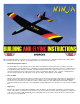
User Manual

.
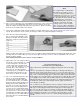
FUSELAGE CONSTRUCTION
NOTE BEFORE BEGINNING:
The Ninja was designed around standard servos (such as the Futaba 848 and Airtronics 94102) that are about 1.5" tall. If
you are planning to use older standard servos that are slightly taller than this, it may be necessary to move up the location
of the outer pushrod hole in former F-2 to fit your particular servo (see step 33). If smaller than standard servos are used, it
will not be necessary to change the pushrod hole location, simply mount the servo a little bit higher.
31.
Carefully remove the die-cut Lite-Ply fuselage sides, top, bottom, formers, and doublers from their sheets. Remove any
rough edges on these parts with a small sanding block with 220 grit sandpaper.
32.
Glue together the two die-cut plywood F-2 pieces using Kwik-Set epoxy or slow C/A. Clamp together or weight down until
dry.
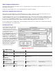
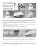
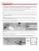
33.
There are two small dimples in the F-2 former. The top center dimple is for the wing hold down dowel; drill this one out with
a 1/4" drill bit. The second dimple that is located near the side of the former, is for the elevator outer nylon pushrod tubing;
drill it out with a 3/16" drill bit.
NOTE:
Even though the NINJA is designed for 2 channels (aileron/elevator), and it flies beautifully that way, some people will
undoubtedly wish to add a third channel for rudder control. If you want to consider this option, refer to "Optional Rudder"
steps 102
-
107 at this time, before going any further.
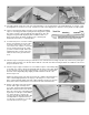
34.
Glue the die-cut plywood fuselage doublers to the die-cut fuselage sides using slow C/A or Kwik-Set epoxy, and allow to
dry. Be sure to make one left side and one right side!
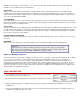
35.
Install former F-2 in it's proper location between both fuselage sides and hold it in place with either masking tape or a
rubber band.
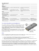
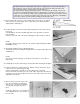
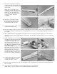
36.
Working from F-2 rearward, slip fuselage formers F-3, F-4, and F-5 into place. Put a rubber band around the fuselage at
each former location to hold it tightly together.
NOTE:
The die-cut notches in the fuselage formers F-3, F-4, and F-5 are for properly locating and gluing in place the outer nylon
push rod tubing. Be sure to position the push rod notches in F
-
4 towards the bottom, as shown in the drawing.