
User Manual

.
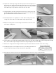
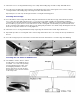
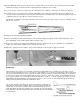
102. Drill an additional 3/16" hole in the opposite side of fuselage former F-2 to accept the outer nylon push rod for the rudder.
NOTE: The fuselage construction must be completed through step 66 before proceeding.
103.
Cut a slot 3/16"x1-1/8" in the fuselage top for the outer nylon push rod tubing to exit through, as shown in the diagram.
104.
Install the 3/16" o.d. outer nylon push rod tubing (SIGSH568) for the rudder by passing it through the pre-drilled hole in
former F-2 and the diecut notches in formers F-3, F-4, and the push rod exit hole in the fuse top. Epoxy glue the outer push
rod tubing in place at each of the fuse formers and to the fuse top.
NOTE: Make sure that the outer push rod extends out in front of former F-
2 for 3/16". Cut the outer push rod tubing oft flush
with the top of the fuse.
105.
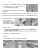
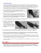
Hinge the fin and rudder with EASY HINGES.
106.
After the fin/rudder assembly is glued in place on the fuselage and properly aligned, install a small molded nylon control
horn (SIGSH220) onto the rudder with two #2 sheet metal screws.
107.
Refer to the elevator servo and pushrod installation procedures elsewhere in this book for guidelines on completing the
rudder servo and pushrod installation on the opposite side of the fuse.
108.
Adjust the control throw of the rudder so that you have minimum of 3/4" left and 3/4" right of movement.
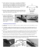
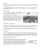
Balancing
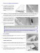
Make a balancer from a block of wood and two pencils that are tipped with erasers. Drill two holes in the block of wood
about 3" apart and install the pencils. To check the fore and aft balance of your model, mount the wing on the fuselage and
place the model in the balancer. The fuselage side view plan shows two locations for balancing the Ninja. The forward C.G.
location is best suited for the first test flights and newcomers to the sport of R/C slope soaring. The rearward location is for
more experienced pilots. The rearward C.G. makes the Ninja more sensitive to control movements, improving it's aerobatic
ability. Balance the Ninja within the recommended C.G. range to suit your needs. Do not attempt to fly the model with the
balance point any further back than the rearward C.G. limit.
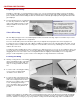
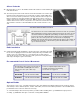
The spanwise balance of the wing is an often overlooked but essential part of
balancing a model. Check the spanwise balance of the wing by placing the wing
upside down on the balancer. Hold the wing level and then release it, observe
which wing panel falls. Add very small amounts of weight to the opposite wing tip
until it will balance. NOTE: Small finishing nails pushed into the end of the wing tip
are ideal for this.