
User Manual

.
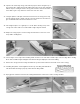
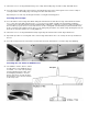
91. Glue the stab in place onto the fuselage. Use slow drying epoxy (SIGEG001) to
allow you ample time to carefully realign the stabilizer with the fuse and wing.
Check and double check the final alignment of the stab to the wing from the front
and top before the glue dries. Step back about 10 feet and view the model from
the front. Tilt the stab for proper alignment if necessary. Use a tape measure to
make sure the stabilizer tips are at equal distances from the trailing edge of the
wing. Use pins to hold the stab securely in position until dry.
92.
Cut away a 1/8" strip of covering material from the center of the stabilizer where
the fin is to be glued. Epoxy glue the fin onto the stab and into the die-cut slot in
the fuselage top at the same time. Use a 90 deg. triangle to align the fin with the
stabilizer, pin securely in place, and allow to dry.
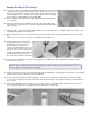
93.
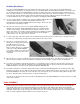
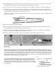
A 1/2"x12" strip of ABS plastic is
provided for a landing skid. Round the
two front corners of the strip with a
sanding block. Apply double-coated
foam servo mounting tape to the plastic
skid, remove the paper backing from the
tape, and press the skid into place.
NOTE: The ABS plastic skid can be
painted a matching color with either
enamel or dope.
Completing The Elevator Pushrod
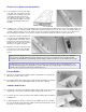
94.
A small nylon control horn has been supplied for the elevator. Install the control horn onto the elevator with #2 x 1/2" sheet
metal screws.
95.
To complete the installation of the nylon elevator pusnrod, first cut one of the 2-56 x 10" threaded rods provided to 3-1/2"
overall length, measuring from the threaded end. Slip the rod completely into the inner pushrod tube and then screw in
about 1/4" of the threaded portion. Screw the nylon R/C link onto the rod leaving a gap of about 1/8" from the end of the
inner pushrod.
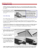
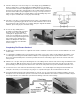
96.
Slide the 1/8" o.d. nylon inner push rod tubing into the outer tubing from the elevator end of the fuselage and attach it to the
nylon control horn. With the elevator level, cut off the protruding end of the inner pushrod 3/8" from the end of the other
pushrod tubing. Unhook the nylon R/C link from the control horn, and push the inner pushrod forward towards the servo.
97.
Locate and cut one of the 2-56 x10" threaded rods provided to 1-1/2" overall length, measuring from the threaded end.
Then put a "Z" bend (or a ''L" bend if you are going to use a pushrod keeper) in the non
-
threaded end of the rod.
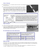
98.
Screw the threaded end of the wire approximately 1/4" into the 1/8" o.d. nylon inner push rod tubing. Install the "Z" bend
through the servo arm and hook it up to the servo and reconnect the R/C link to the elevator control horn. NOTE: It may be
necessary to trim the servo arm down to prevent it from rubbing on the side of the fuselage.