
User Manual

.
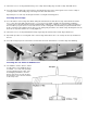
Elevator Servo And Pushrod Installation
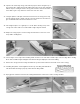
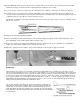
64.
Cut a small piece of 1/16" scrap balsa,
3/16" wide x1/2" long. Glue it onto the
fuselage bottom sheeting, in the push
rod slot at the bottom of former F-5.
(See drawing.) This shim is to elevate
the entire pushrod slightly to keep the
R/C link from rubbing on the bottom
sheeting.
65.
Install the 3/16" o.d. nylon outer pushrod tubing by passing it through the pre-drilled hole in former F-2 and through the die-
cut notches in F-3, F-4, and F-5. Make sure the tube extends past former F-5 for 1/4". Also, make sure that the other end
extends forward of former F-2 for 3/16". When you have the length properly determined, cut off the excess. Then epoxy
glue the tubing permanently to each of the fuse formers and to the fuselage side between formers F
-
2 and F
-
3.
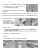
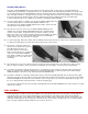
66.
For adequate servo arm clearance, the
servo must be moved slightly inboard.
Using the pattern on the plan, make a
spacer for the servo from 3/32" balsa,
and glue it to the inside of the fuselage
where the servo will be mounted.
67.
Apply the servo tape to the back of the
servo and remove the paper backing.
Press the servo onto the 3/32" balsa
spacer.
BUILDER'S TIP: Apply a thin coat of slow C/A to the balsa spacer and allow the glue to dry before taping the
servo in place. This will greatly increase the bond of the servo tape. The remainder of the elevator pushrod
installation details will be done later during "Final Assembly", after the tail surfaces are mounted to the fuselage.
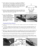
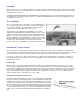
FLYER'S TIP: If you are new to the sport of slope soaring or your favorite site has a rough landing area, we
recommend reinforcing the fuselage with 3/4 oz. glass cloth and epoxy. Apply the glass cloth and epoxy to the
outside of the fuselage from former F-4 forward to the nose.
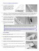
Fin And Rudder
68.
Glue the die-cut balsa fin and rudder together using medium viscosity C/A glue.
When dry, sand the seam smooth.
69.
Round the leading edge, trailing edge, and the tip with a sanding block and 150
grit sandpaper. Do not sand the alignment tab on the bottom of the fin.
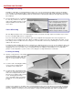
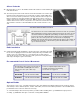
Stabilizer And Elevator
70.
Sand the pre-cut 3/16" balsa stabilizer leading edges round except for the short
length in the center, which should be left flat to fit against the back of F-5.
71.
Locate the pre-cut 3/16" balsa elevator and sand the leading edge round with a
sanding block.
72.
Temporarily tape the elevator to the back of the stabilizer, then use a sanding
block to sand both of them at the tips until they match perfectly. The tips can be
left square or sanded round if you prefer.