When designing the Ninja, our goal was to insure that it was one of the finest slope soaring kits available on the market (what else would you expect from a Sig kit?). The design parameters we followed are listed below: 1. Outstanding Flight Performance The model had to be very forgiving and easy to fly with no bad habits for low-time pilots. Also, it had to be aerobatic enough to please even the hottest flyers.
. Radio Equipment Requirements The Ninja requires only elevator and aileron control, so any radio with 2 or more channels may be used as long as it is on an aircraft approved frequency. NOTE: If the optional rudder is to be used, a radio with at least 3 channels is required. Notes Before Beginning Construction Any references to left or right refer to your left and right as if you could be seated in the cockpit of the model.
. Die-Cut Birch Plywood 1 1/16"x3"x6" F-2 Fuse Former Foam I Foam Wing Core Hardwood I 3/8"x5/8"x I-5/8" Basswood 2 1/4"x3/8"x I" Basswood Servo Mounts Wing Hold Down Block I 1/4" dia.x1-1/12" Birch Wing HoldDown Dowel Formed Wire Parts I 1/32"dia. Canopy Latch 1 4-40x8" threaded rod L.H. Aileron Torque Rod (with 1/8" o.d.x4" brass bearing) I 4-40x8" threaded rod R.H. Aileron Torque Rod (with 1/8" o.d.
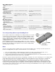
. SIG CA, like most brands of cyanoacrylates, comes in three viscosities thin, medium, and thick. An accelerator spray and debonder are also available and are described below. SIG CA THIN Watery in consistency, thin C/A should only be used when the two parts to be joined are in perfect contact with zero gap. Capillary action pulls this glue deep into the wood resulting in a very strong bond and it dries in just a few seconds.
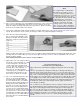
. THE SECRET OF A PERFECT FOAM WING 4. It's a simple matter of a FLAT table. Most tables are not flat, as can be seen by checking them with a good straightedge. If a foam core is covered on a bowed or twisted surface, then the wing will be bowed or twisted. And a table that checks out true but is flexible and will yield as you press on it will also spoil a wing. The ideal Place a sheet of wax paper onto your building board.
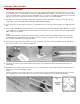
. 9. Roll the foam core forward onto the wing skin with a rocking motion until the entire skin is attached. 10. Trim off most of the excess balsa wing skin, to within about 1/16" of the foam core, with a sharp single-edge razor blade or a modeling knife. It is not necessary to trim the balsa completely flush with the foam wing core at this time. 11. Repeat steps 1 through 10 to skin the other three sides of the foam cores. 12.
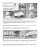
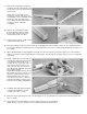
. 19. The angle already cut into the ends of the foam wing halves sets an approximate correct dihedral angle. To check it, set up the wing halves as shown. If necessary, sand the root ends of the wing panels to make the center joint fit correctly together. 20. Using a soft lead pencil, mark center lines on the leading and trailing edges of each wing panel. When joining the two wing panels together, line up these marks to properly align the two wing panels.
. An alternate method of attaching the glass tape is to lightly spray one side of the tape with a spray adhesive (such as 3M "77"). Place the tape on the wing joint (sticky side down) and smooth out any wrinkles. Soak the glass tape with thin C/A. The spray adhesive simply holds the tape in place - it won't affect the strength of the C/A. A second coat of C/A will help fill in the weave of the fiberglass, resulting in a smoother surface.
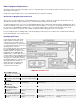
. FUSELAGE CONSTRUCTION NOTE BEFORE BEGINNING: The Ninja was designed around standard servos (such as the Futaba 848 and Airtronics 94102) that are about 1.5" tall. If you are planning to use older standard servos that are slightly taller than this, it may be necessary to move up the location of the outer pushrod hole in former F-2 to fit your particular servo (see step 33).
. 37. Slide the die-cut Lite-Ply fuselage top rearward, under the rubber bands, until it snaps into it's proper location between the fuse sides. NOTE: The Tee-Lock tabs on the fuselage top, bottom, and formers are made slightly oversize and will protrude past the fuselage sides at this time. These will be sanded off later after the fuselage has been completely assembled . 38.
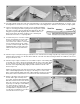
. 46. Tape the die-cut Lite-Ply canopy sides in their proper locations along the top of the fuselage sides. Slide former F-2A down between the canopy sides until flush with the top of F-2 and glue it to the canopy sides. Extreme care must be taken to insure that no glue seeps down onto former F-2 or the fuse sides. 47. Using the pattern on the plan, make the front former for the canopy from scrap Lite-Ply and glue in place.
. Mounting The Wing To The Fuselage 54. Locate the 1/4" dia. x1-1/2" wing hold down dowel and sharpen one end to a point - keep the point symmetrical and centered. Push the dowel into the hole in F-2 so that only the point remains sticking out into the wing opening. Slide the wing into position, making sure it is centered on the fuselage. When you remove the wing, there should be a small indentation in the leading edge. 55. Drill a 1/4" diameter hole through the leading edge at the indentation.
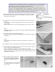
. Elevator Servo And Pushrod Installation 64. Cut a small piece of 1/16" scrap balsa, 3/16" wide x1/2" long. Glue it onto the fuselage bottom sheeting, in the push rod slot at the bottom of former F-5. (See drawing.) This shim is to elevate the entire pushrod slightly to keep the R/C link from rubbing on the bottom sheeting. 65. Install the 3/16" o.d. nylon outer pushrod tubing by passing it through the pre-drilled hole in former F-2 and through the diecut notches in F-3, F-4, and F-5.
. COVERING AND FINISHING Preparing For Covering Regardless of what type of covering material you elect to use, a good covering job starts with good surface preparation. You can't hide poor workmanship with covering material! Fill any small surface gaps with a light-weight filler or spackling paste. Sand the entire model including the ailerons and tail surfaces, with 220 grit sandpaper, then again with 360 or 400 grit sandpaper. 73. The structure that is to be covered must be clean, dry, and dust free.
. 77. Trim off the excess covering material leaving a 1/8" overlap at the trailing edge. Seal the overlap down with an iron. 78. Cover the top of the wing in the same manner as described in the above steps 74 through 76. Leave a 3/16" overlap of covering material on the leading edge of the wing and seal it down with an iron. Repeat the process from steps 74 through 78 to finish covering the other wing panel. Covering The Fuselage 79. Cover the bottom of the fuselage first.
. Installing Easy Hinges Sig's famous EASY HINGES have been included in your kit to hinge all the control surfaces. Each ultra-thin hinge is actually a three-part laminate, a tough plastic inner core sandwiched by an absorbant wicking material on each side. They are specially designed to be installed with thin C/A glue.
. 91. Glue the stab in place onto the fuselage. Use slow drying epoxy (SIGEG001) to allow you ample time to carefully realign the stabilizer with the fuse and wing. Check and double check the final alignment of the stab to the wing from the front and top before the glue dries. Step back about 10 feet and view the model from the front. Tilt the stab for proper alignment if necessary. Use a tape measure to make sure the stabilizer tips are at equal distances from the trailing edge of the wing.
. Aileron Pushrods 99. Mount the aileron servo to the hardwood rails in the manner recommended by the radio manufacturer. 100. The aileron pushrods are made from two 2-56 x10" threaded rods. Screw a nylon R/C link onto the threaded end of each rod. Next screw the self-threading nylon aileron connectors that are provided 1/4 of the way down the aileron torque rods that are sticking out of the wing. Snap the R/C links into the aileron connectors and line up the pushrods with the servo arms.
. 102. Drill an additional 3/16" hole in the opposite side of fuselage former F-2 to accept the outer nylon push rod for the rudder. NOTE: The fuselage construction must be completed through step 66 before proceeding. 103. Cut a slot 3/16"x1-1/8" in the fuselage top for the outer nylon push rod tubing to exit through, as shown in the diagram. 104. Install the 3/16" o.d.
. Pre-Flight Make sure the servos are securely mounted, the servo arms have their retaining screws in place, and all screws are tight. Range check the radio as per the manufacturer's instructions and make sure it is fully charged. If there are any problems, send the radio in for repairs.
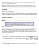
. Ballast The clean lines and the low frontal area of the Ninja allow it to penetrate winds in the 10-20 m.p.h. range without ballast. However, when flying in winds of excess of 20 m.p.h. some ballast may be needed. Stick-on lead weights are ideal for adding ballast. Simply press them in place inside the fuselage directly over the C.G.
. It will take a little practice to master the art of slope soaring, but it is well worth the effort and a lot of fun. So, next time the wind blows, grab your Ninja and head for your favorite slope. LIMIT OF LIABILITY: In use of our products, Sig Mfg. Co.'s only obligation shall be to replace such quantity of the product proven to be defective. User shall determine the suitability of the product for his or her intended use and shall assume all risk and liability in connection therewith.