INTRODUCTION The RISER 100 is a standard class sailplane designed for sport and competition glider pilots alike. It's everything a "glider guider" could want in an all around sailplane - ease of building, large size, and great "hang time"! With a 100 inch wingspan and 1000 sq. in. of wing area, the RISER 100 is one of the best floaters around. A modified Eppler-205 airfoil lets the RISER 100 maximize any available lift, while still allowing excellent penetration on windy days.
. Notes Before Beginning Construction Any references to right or left refers to your right or left as if you were seated in the cockpit. References to inboard means toward the fuselage, while references to outboard means away from the fuselage. To build good flying models, you need a good straight building board. Crooked models don't fly well! The building board can be a table, a workbench, a reject "door core" from the lumber yard, or whatever - as long as it is perfectly flat and untwisted.
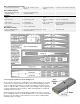
. Die-Cut Poplar Plywood (Lite-Ply) 1 1/8"x6"x48" Fuselage Sides 1 1/8"x6"x20" Fuselage Top and Formers 1 1/8"x3"x48" Fuselage Bottom 1 1/8"x6"x12" W1A and W1B Wing Ribs Die-Cut Birch Plywood 1 3/32"x4"x6" Servo Rails and Polyhedral Braces 1 1/16"x4"x6" Rib Guages and Fuselarge Doublers Hardware 2 9/32" o.d.
. Finally, glue sandpaper onto different sizes of scrap plywood sticks and round hardwood dowels. These are handy for working in tight places and for careful shaping where a big block is too hard to control. Glues There are so many different glues available today for model construction that it can be confusing even for the experienced modeler. To simplify matters, most glues can be classified as one of four basic types: 1. 2. 3. 4.
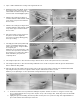
. 2. Tape or rubber band the two fuselage sides together at the rear. 3. Working from the rear forward, slip all of the fuselage formers into place. Put a rubber band around the fuselage at each former location to hold it tightly together. 4. Slide the die-cut lite-ply fuselage top rearward, under the rubber bands, until it snaps into it's proper location between the fuse sides. 5.
. 12. Glue and pin in place the 2"x2-1/4"x3" balsa nose block. It should be flush with the bottom of the fuselage. 13. Roughly carve the nose block and top hatch sheet to shape as shown on the plans. A razor plane or a #26 X-Acto blade and handle are ideal for this step. 14. Sand the nose block and the top hatch to exact shape with a sanding block and remove the top hatch from the fuselage. 15. Carefully remove the 12" long portion of the top hatch from the fuse sides.
. 21. Drill a hole through the bottom of the fuselage and through the fuselage doubler FD for the towhook mounting. Measure the exact location for this hole carefully from the plan, as the towhook position is critical for achieving a good launch of the sailplane. Install a 4-40 blind nut in the hole on the inside of the fuselage. 22. The fuselage is now ready for final sanding. Sand off all "Tee-Lock" stubsa and round the edges of the fuselage with a sanding block.
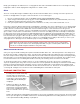
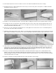
. WING CONSTRUCTION Left Inboard Panel 28. a. Begin by pinning in place the 5/16"x1-1/4"x26" notched balsa trailing edge over the plans. NOTE: Make sure that you identify the correct trailing edge for each of the four wing panels, the notch spacing is different for each. b. Pin in place the 3/16"x3/8"x25" bottom spruce spar, making sure you leave a small amount of excess on each end of the wing panel. NOTE: Use two W-2 ribs to position the spar the proper distance from the trailing edge. c.
. Wing Center Section 35. a. Install a piece of 9/32" o.d. x4" brass tubing into the holes in the W1A and W1B ribs. Do the same for both inboard wing panels. NOTE: Do not glue the brass tubes to the ribs at this time. Next, slide the 1/4" music wire joiner inside the brass tubes, joining the two inboard wing panels together. b. With the center joint firmly down against the workbench, block up each end of the wing panels 1-1/2".
. 43. Also, drill 1/8" holes through the W1B and W-2 ribs shown on the plan to allow the plastic tubing to pass through them. In addition, cut a small hole in the bottom center sheeting, just behind the spruce spar, where the plastic tube should exit the wing. Carefully slide the plastic tubing in place, using a heat gun where necessary to soften the plastic tubing just enough to allow it to be bent into shape. Glue the tubing securely to the ribs and to the bottom sheeting. 44.
. 46. Cut out the rib notch pattern. Tape it in place on Rib W1A, and then notch out the rib as per pattern. 47. With a sanding block, bevel one end of each 3/8"x1-5/16"x2-7/16" balsa wing block to match the angle of the W1A rib. Epoxy glue the blocks in place between the ribs W1A and W1B of each wing panel. Use a T-square to make sure the blocks are 90 deg. to the W1A rib and against the back side of the leading edge. 48.
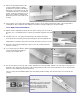
. Outer Left Panel 55. a. Pin in place the 5/16"x1-1/4" notched balsa trailing edge over the plans. Make sure that you have the correct trailing edge for each panel. b. Pin in place the 3/16"x3/8"x24" spruce spar, making sure you leave a small amount of excess on each end of the wing panel. 56. Glue and pin ribs W-3, W-4, W-5, W-6, W-7, and W-8 in place on the spar and to the trailing edge. Do not glue in the W-2 rib at the polyhedral joint yet. 57.
. 66. Pin down the inboard panel over the plan. Position the outboard panel on the plan against the inboard panel and raise the wing tip 3-3/4" as shown. If the joint between the two panels does not match perfectly, sand one or both of the ribs until it does. Glue the panels together with epoxy glue. Have a wet joint to insure that the glue will fill any gaps in the seam. After the epoxy has set up, take up the wing panels and peel off any excess glue that has squeezed out. 67.
. 73. Disassemble the wing panels and cut off the dowel pin so that only 3/4" sticks out of the left wing panel W1A rib. Round the end of the dowel pin with sandpaper. STABILIZER AND ELEVATOR 74. Use a modeling knife or a jig saw to cut all of the tail surface parts (S-1, S-2, S3, FG, RG-1, and the Dorsal Fin) out of the 1/4" printed balsa sheet. Be sure to cut just outside of the line. 75. Sand stab parts S-1, S-2, and S-3 down to the line with a sanding block. 76.
. FIN AND RUDDER 84. Cut the rudder pattern from plan Plate 2 and tape it in place right behind the fin plan on Plate 1. 85. Glue and pin all pieces of 1/4"x5/16" balsa for the fin and rudder in place over the plans. 86. Glue and pin the balsa dorsal fin and gussets FG, RG-1 and RG-2 in place. 87. Cut pieces of 1/8"x1/4" balsa for the cross bracing and glue in place as shown on the plans. 88. Block sand both sides of the fin and rudder to remove any rough areas. Be sure to sand the print off the wood. 89.
. COVERING All of the RISER 100 prototypes were covered with Sig Supercoat Iron-On Plastic Covering. The covering is ideal for sailplanes because of it's light weight and ease of application. Start by covering the wing from the main spar to the trailing edge with Transparent Blue. Next, cover the wing panel from the spar forward to the leading edge with White. The white should overlap the Blue about 1/2" at the spar! Follow the same procedures to cover the top and bottom of all four wing panels.
. Move the heat gun or iron back and forth over the surface of the wing, allowing the heat to shrink all of the covering on that side at the same rate. Keep the heat gun moving at all times, about 4" to 6" above the covering. If you stop moving for too long, or hold the gun too close, you might melt a hole in the covering. If you notice that the covering material is "ballooning-up" and not shrinking completely, put a small pin hole in the bottom of each rib bay to allow expanding air to escape. 97.
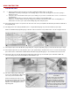
. INSTALLING EASY HINGES 105. Using a No. 11 X-Acto blade (or similar) cut slots in the control surfaces approximately 1/2" in depth and slightly wider than the hinge at the locations shown on the plans. Continue cutting all of the slots in all the places to be hinged. 106. After all slots have been cut, insert an EASY HINGE halfway into each slot in one of the pieces to be hinged. DO NOT GLUE THE HINGES YET! First carefully slide the matching model part onto the other half of the hinges.
. 114. Epoxy the fin permanently onto the stabilizer and into the die-cut slot in the fuselage top at the same time. Also, insert the bottom rudder hinge into the fuselage when gluing the fin in place. Use a triangle to align the fin with the stabilizer, pin securely in place, and allow to dry. Glue the bottom hinge into the rudder and fuselage with thin variety CA glue, as was done for all the other hinges. 115. Draw a pencil line down the center of the fuselage bottom to help align the ABS plastic skid.
. 123. The installation of the spoilers can now be completed. Two 3/64" x 1-3/8" wires, with a loop in one end, are provided for making spoiler actuator wires. Finish shaping these wires by bending them with pliers to match the pattern shown. Then epoxy one of the wires in place on the bottom of each spoiler, directly in line with the end of the plastic tubing in the wing. 124. Two 1/2"x3/4" pieces of lead are provided for spoiler closing weights.
. Pre-Flight Make sure the servos are securely mounted, the servo arms have their retaining screws in place, and all screws are tight. Range check your radio as per the manufacturer's instructions and make sure it is fully charged. If there are any problems, send the radio in for repairs.
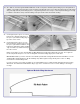
. Thermals are normally small near the ground and tend to increase in diameter the higher up they go. To get into a thermal, we must first gain some altitude. There are two commonly used methods of launching a sailplane into the air. HIGH-START: A high-start is made up of surgical tubing and nylon cord. Its purpose is to "sling-shot" the glider into the air like a large rubber band launched model.
. Now that the sailplane is at altitude, it is time to go thermal hunting. Start by trimming the RISER 100 for a nice flat glide and head upwind flying a zig-zag pattern. Never cover the same ground twice while searching for thermals. Be looking for areas where you can see heat waves radiating up, or hawks circling, or swirling "dust devils" being picked up off the ground. Remember, smooth flying is the secret to long flights. Watch the sailplane closely as it is flying.
. If you have any technical questions or comments about this kit, or any other SIG product, please call us. SIG MODELER'S HOTLINE 1-800-524-7805 Weekdays, 7:00am - 4.30pm Central © Copyright SIG Mfg. Co., Inc. SIG MFG. CO., INC............Montezuma, Iowa 50171-0520 LIMIT OF LIABILITY: In use of our products, Sig Mfg. Co.'s only obligation shall be to replace such quantity of the product proven to be defective.