INTRODUCTION Sailplanes are an easy and relaxing way to learn and enjoy radio control flying. To fly them well, however, takes a lot of skill and knowledge about the air in which they fly. The RISER was designed with the beginner and sport flier in mind to create a "floater" that's docile and predictable in flight. The RISER'S gentle handling characteristics doesn't mean it lacks performance. Experts will find the RISER is capable of holding its own in two-meter sailplane competition.
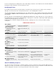
. Don't use a ball point pen for making marks on the model during construction. If not sanded off, these ink marks will show through the model's final finish. Use a pencil instead of a pen. Identifying Kit Parts Leave all die-cut parts in the sheets until needed in construction. Then remove the pieces from the sheets carefully. If difficulty is encountered, do not force the part from the sheet - use a modeling knife to cut it free. The die-cut balsa wing ribs are identified below.
. Keep in mind that the numbering sequence used in these instructions was chosen as the best way to explain the building of each major component and is not intended to be followed in exact one-two-three fashion. Start on the wing at NO.1 and after doing as many steps as is convenient, flip over to "FUSELAGE CONSTRUCTION" and do a step or two there, then over to "TAIL SURFACECONSTRUCTION" and so forth. You will, of course, arrive at points where you can go no farther until another component is available.
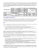
. You can't get along without a good sanding block An assortment of different size sanding blocks are indispensable tools for model construction. A good general purpose block can be made by wrapping a 9"x11" sheet of sandpaper around a piece of hardwood or plywood. Use three screws along one edge to hold the overlapped ends of the sandpaper. Put 80-grit paper on the block during general construction. Switch to 220-grit paper for final finish sanding just before covering.
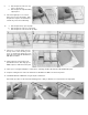
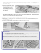
. 8. 9. 10. a. Glue and pin the 3/16"x1/4" top spruce spar in place. b. Glue and pin the shaped leading edge in place. Cut vertical grain pieces of 1/16"x3" balsa sheet for spar shear webs. Glue and pin these in place. Note that these extend oniy out to the fourth rib bay. a. Glue and pin the top spar cap strip. b. Glue and pin the 1/16"x1" top sheeting. c. Glue and pin the 1/16"x3/16" rib cap strips. 11. Cut pieces of 1/16"x3" balsa sheet for the top center section sheeting.
. Outboard Wing 16. a. Pin down the 1/16"x1" bottom sheeting. b. Pin down the 1/16"x3/16" spar cap strip. c. Pin down the 1/4"x1" trailing edge over the plans. 17. Cut pieces of 1/16"x3/16" balsa for the bottom rib cap strips. Glue and pin these as indicated on the plans. 18. Glue and pin the 1/8"x1/4" spruce spar on top of the 1/16"x3/16" spar cap strip. Use a few ribs to locate the spruce spar in relation to the trailing edge. 19. Glue and pin down the ribs (except W·2) in place.
. 26. Glue and pin the 1/8"x1/4" spruce top spar in place. 27. a. Glue the 1/16"x3/16" top spar cap strip on top of the spar. b. Glue and pin the 1/16"x1" top sheeting in place. 28. a. Cut pieces of 1/16"x3/16" balsa for top rib cap strips. b. Glue and pin the cap strips in place. 29. Glue wing gusset WGT in place as indicated on the plans. 30. Block sand the entire wing panel to smooth out any rough surfaces. 31. Tape a piece of 80 grit sandpaper to a flat surface. Carefully sand the dihedral joint.
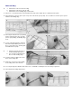
. 39. Use the patterns supplied to make two WTT's and two WTB's. Cut these from the scrap 3/32" die-cut plywood brace WR. 40. Trial fit the dihedral braces WTT & WTB. Trim the ribs if necessary, but do not glue the dihedral braces in yet. Repeat these procedures for the other outboard wing panel so that you will have one left panel and one right panel. 41. Carve the leading edge of all wing panels with a single edge razor blade to airfoil contour. Joining Wing Panels 42.
. STOP: If you wish to add the spoiler option it.js best to do it before proceeding to the next step. (See "Optional Spoilers" at the end of this section). 44. Position the two wing halves over the plan. Pin the right half down so that its inboard panel is flat on the plan. Block up the left wing half 2-3/4" at the inboard-outboard joint. If the joint between the right and left wings do not match perfectly, sand one or both of the ribs until it does. 45. Glue the panels together with epoxy glue.
. 4. Cut a piece of 1/16" x 1/2" balsa sheeting and glue in place on top of the 1/8" sq. balsa and flush with the top of the wing. 5. Cut a piece of 3/16" x 1/4" balsa to fit in between the ribs as shown on the plans. Drill a 1/8" hole through the center of it to allow the plastic tubing to fit through. Glue the balsa piece in place. 6. Using heat, pre-bend the plastic tubing to the shape shown on the plans.
.
.
. FUSELAGE CONSTRUCTION 49. Drill or cut out the 5/32" dowel holes in the fuselage sides. This will locate the holes after the plywood doublers have been glued in place. 50. a. Cut pieces of 1/4" triangle stock, and b. 1/8"x3/16" balsa as indicated on the printed fuselage sides. 51. Glue and pin the 1/4" triangle stock pieces and 1/8"x3/16" pieces in place. 52. Using a paddle, spread a thin coat of epoxy glue on both die-cut 1/32" plywood doubler's FDF.
. 60. Pin the side in position over the top view of the plan. 61. Epoxy glue the other fuselage side to F-2 and F-3 over the plans. Check with a square before the glue sets up. 62. Pull the fuselage sides together at the rear using square weights (pieces of scrap iron shown here) and glue together. 63. Epoxy glue both sides of F-1 and glue in place over the plans. Pin or use weights to hold the sides until the glue sets up. 64.
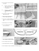
. 70. Secure the servo, using the manufacturer's mount or mount on hardwood rails. See "Radio Installation" for more information on mounting servos. 71. Cut off 2-1/2" at the threaded end of one of the threaded rods. Put a "Z" bend (or a "L" bend if you are going to use a pushrod keeper) in the non-threaded area of the rod. 72. Clean the threaded area with a rag dipped in alcohol or thinner. This will remove any oil from the wire. Thread the wire into the inner tubing.
. 80. Mark a line 3" from the end on the fuselage top hatch sheet (1/4"x2-1/4"x8" balsa). This will indicate where to cut the hatch apart from the rest of the top. 81. Tack glue the top hatch sheet onto the fuselage. The front should be flush with F-1. 82. Use a single-edge razor blade to trim the top hatch sheet flush with the fuselage sides. 83. Smooth the rough edges with a sanding block. 84. Saw along the line previously marked to cut the hatch apart from the rest of the top. 85.
. 92. Block sand all edges to smooth out any rough areas. 93. Remove the hatch and glue in a piece of scrap 1/8" Lite-ply for the hatch holddown plate "HH" as indicated on the plans. Drill through hatch for the 256x1/2" hold-down screw. 94. Glue a piece of scrap 1/32" plywood (hatch tongue) to the front of the hatch on the bottom side as indicated on the plans. 95. Drill the dowel holes on through the plywood doublers for the 5/32" wing hold-down dowels.
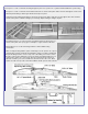
. 101. Glue and pin the 1/8"x3/16" cross braces in place over the plan. 102. Completed stabilizer ready for sanding. 103. Block sand the stabilizer to smooth any rough areas. Be sure to sand the print off of the wood. 104. With a sanding block, shape the tips as indicated on the plans. Round the leading edge and the tips. 105. Pin the elevators over the plans. Trial fit the 3/16" square x4" spruce joiner. 106. Glue the spruce joiner in place. 107. Block sand the elevator.
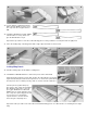
. 112. Block sand all pieces. 113. Round all edges with a sanding block. 114. Cut a slot in the fuselage top for the fin tab. 115. Trial fit the fin tab into the slot. Do not glue the fin into place yet. FINAL ASSEMBLY 116. Cover the stabilizer and elevator using the procedures outlined in the "COVERING" section. Once they are covered, install the Easy Hinges as described below. Use four hinges located as shown on the plan. 117. Cover the fin and rudder as you did in the prior step, and install the hinges.
. 120. Remove the covering material from the top of the stabilizer and fuselage where the fin makes contact. Epoxy glue the fin in place. Use a square to make sure that the fin is perpendicular to the stabilizer. Developed from the start to take advantage of the popular cyanoacrylate adhesives, EASYHINGES are fast, strong, and lightweight. With these hinges, there is finally a solution to the dreaded, tedious job of hinging control surfaces. No more gouging and picking to make oversize slots in the wood.
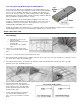
. Follow their instructions closely when applying the material, as different brand coverings can have slightly different handling characteristics and application temperatures. However, the basic techniques for applying iron-on plastic coverings of any brand are similar, and the following hints and photos should be helpful. NOTE: The structure shown is of a different model but the same procedures are used. 1. The structure that is to be covered must be clean, dry, and dustfree.
. 9. Cover the bottom of a fuselage first. When doing compound curves, as on the nose shown here, be sure to leave extra material around that area. Grip the covering and apply heat. As the covering becomes pliable pull the covering around the curve. Work slowly and cover small sections at a time. 10. Trim off excess and seal edges. Repeat this procedure on the sides. Allow about 1/8" to 1/4" overlap for a fuel-proof seam. 11. Cover the top and seal down all edges. 12.
. Elevator And Rudder Hookup Attach a small nylon control horn to the rudder and another to the elevator using #2x1/2" sheet metal screws. Mount the rudder control horn to the left side of the rudder and the elevator control horn on the bottom of the right elevator half, as shown on the plans. Slide an inner nylon pushrod into its outer sleeve and attach the Z-bend to the servo arm as you did in Step 73. Be certain to completely tighten the small servo screw that holds on the servo arm.
. Airplanes Must Be Straight And Balanced (or straighten up and fly right!) One of the secrets to a good flying model is to make sure the wing is straight and the model is properly balanced. Check to make sure there are no warps in the wing. If there are, twist the wing in the opposite direction of the warp and apply heat to both sides of the covering material, starting on the side opposite the warp. Hold until the covering cools, then recheck for straightness. Try again if necessary.
. The main thing to remember when flying a sailplane is not to over control. If the model does get out of control, and you have sufficient altitude, a glider is so stable that you can usually just let go of the sticks momentarily and the model will right itself. Many models have crashed because a beginner continued to send the wrong input.
. Now that the sailplane is at altitude, it is time to go thermal hunting. Start by trimming the RISER for a nice flat glide and head upwind flying a zig-zag pattern. Never cover the same ground twice while searching for thermals. Be looking for areas where you can see heat waves radiating up, or hawks circling, or swirling "dust devils" being picked up off the ground. Remember, smooth flying is the secret to long flights. Watch the sailplane closely as it is flying.
. If you have any technical questions or comments about this kit, or any other SIG product, please call us. SIG MODELER'S HOTLINE 1-800-524-7805 Weekdays, 7:00am - 4.30pm Central © Copyright SIG Mfg. Co., Inc. SIG MFG. CO., INC............Montezuma, Iowa 50171-0520 LIMIT OF LIABILITY: In use of our products, Sig Mfg. Co.'s only obligation shall be to replace such quantity of the product proven to be defective.