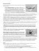
. Design Philosophy When developing the Four-Star 40, two design considerations were at the top of the list in importance: Impeccable Flight Performance - Like all Sig kits, it had to have smooth, reliable flight performance with no surprises. It had to fly through maneuvers, not just be pulled through by brute force of the engine. Gentle slow speed and stall characteristics were equally important.
. Each of these types has different characteristics and advantages. Often times, the choice of which type to use is strictly a matter of personal preference based on your experience with a previous model. However, because of the vast use of LitePly and hardwoods in the FOUR-STAR 120, we have found that the CA glues seem to work the best for general construction. In fact, the construction sequence of the fuselage is designed with the use of CA glue in mind.
. You'll Need a Good Sanding Block An assortment of different size sanding blocks are indispensable tools for model construction. A good general purpose block can be made by wrapping a 9"x11" sheet of sandpaper around a piece of hardwood or plywood. Use three screws along one edge to hold the overlapped ends of the sandpaper. Put 80-grit paper on the block during general construction. Switch to 220-grit paper for final finish sanding just before covering.
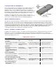
. Sawn Birch Plywood 2 1/16"x3/4"x1-5/8" Wing 1 Hold Down Plates Hardwood I 1/4" dia.x2" BIRCH; 2 Wing Hold Down Dowel Formed Wire Parts 1 1/16" dia. Tailwheel Wire Formed Plastic 1 .03 Clear Plastic; Canopy Miscellaneous Parts 2 Glass Filled Engine Mounts 1I 10"x27" Decal Hardware 4 #2x1/2" Sheet Metal Screws (for control horns) 7 6-32 Blind Nuts (4/engine mounts, 3/1anding gears) 5 2-56 R/C Links (2/ailerons, I/elevator, l/rudder, I/throttle) 1 .130"o.d.
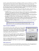
. WING CONSTRUCTION Building The Wing Panels 1. 2. 3. Before beginning wing construction, carefully splice together the Left Wing Panel plans so that the "X" and "Y" indicators meet. Use a straightedge to double check the alignment of the plans before taping them at the seam. Tape or pin the plans to your building board and protect them with a layer of waxed paper. Build each wing half separately. a. Pin the 3/16"x3/8"x30" spruce main wing spar in place on the plan.
. 4. Install a pre-cut 3/32"x3"x1-3/16" balsa shear web in each rib bay except the one between the two most inboard W-1 ribs (where the dihedral brace will be installed later). Notice that the wood grain is vertical for maximum strength. Trial fit each web before gluing, sanding the ends as necessary to make them fit snugly between the ribs on either side.
. 11. Carefully carve the top of the trailing edge to match the slope of the top T.E. sheeting using an X-Acto #26 whittling blade. Wrap the top of the blade with masking tape (to protect the sheeting), leaving about 1/2" exposed at the base. Use the masked portion to guide the blade at the corred angle. Final sand the T.E. so that the back edge of the wing is about 1/4" thick (same as the ailerons). 12. Glue the die-cut Lite-Ply wingtip to the outboard end of the wing panel.
. 16. a. When dry, double check through the servo opening on top and the center sheeting opening on the bottom that the dihedral brace is glued solidly to the main wing spars and the W-1 wing ribs. b. Glue the die-cut balsa piece BP into the aft end of the servo opening. When dry, trim BP flush with the top center sheeting. 17. a. The aileron torque rods have been pre-bent so that the threaded portion leans forward slightly inside the fuselage (see the W-1 wing rib crosssection on the plans).
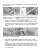
. METHOD 1: 1. Coat the wing center joint with slowdrying epoxy glue. 2. Lay the tape on top of the glue. 3. Holding one end of the tape so it won't slip, "squeegee" the glue through the tape with a small paddle of scrap balsa. Scrape over the tape several times with the paddle to smooth the tape and remove any excess glue. 4. When dry, sand lightly to remove any rough spots. Try not to sand into the fiberglass tape itself. METHOD 2: (Shown in the photo) 1.
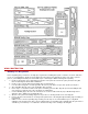
. FUSELAGE CONSTRUCTION Before starting fuselage construction, there are a few subassemblies that should be built and set aside until needed. This is done to avoid interruptions during the flow of fuselage construction. Fuselage Subassemblies 26. a. Glue together the two die-cut plywood F-1 pieces using KwikSet Epoxy or slow CA. Use a heavy weight of some kind to hold the two pieces perfectly flat while drying. b.
. Basic Fuselage Construction 32. a. Tape or rubber band the fuselage sides together at the rear. b. Working from the rear forward, slip all the fuselage formers (F-6 thru F-1) into place. Put a rubber band around the fuselage at each former location to hold it tightly together. c. Slide the die-cut Lite-Ply part FBR (fuselage bottom, rear) under the rubber bands until it snaps into its proper location between the fuselage sides. d. Slide the cockpit floor into place under the rubber bands.
. 39. The fuselage is now ready for final sanding. Sand off all "Tee-Lock" tabs then round the bottom edges of the fuselage and the corners of the balsa top deck. Use a sanding block, starting with 80-grit sandpaper. Switch to 150-grit or 220-grit sandpaper for the final sanding. Mounting The Wing To The Fuselage NOTE: The wing must be finished through step 19 before proceeding. 40. Locate the 1/4"dia.x2" wing hold-down dowel and sharpen one end to a point - keep the point symmetrical and centered.
. 44. a. Remove the wing and tap the wing hold-down blocks with a 1/4-20 tap. You can apply a few drops of thin CA to the holes to strengthen the threads. b. Redrill the holes in the wing with a 1/4" drill bit to pass the nylon wing bolts. Servo And Pushrod Installation 45. Now is a good time to plan your servo installation. Refer to Chapter 2 of "The Basics of Radio Control", and the plans for information on where and how to mount the servos in the fuselage.
. 50. With the pushrods hooked up to the servos, you can now glue F-3S and F-4S to the front of F-3 and F-4, respectively, in such a way to keep the bends at a minimum. 51. This is a good time to install the nylon outer tubing for the throttle pushrod. Temporarily mount your engine to help locate where the throttle pushrod will come through F-1. Follow the guidelines given in "The Basics of Radio Control" (page 8), but stop before attaching the solder clevis (servo connector).
. All of the Four-Star 40 prototypes were covered with Sig Supercoat Iron-On Plastic Covering. Supercoat is ideal for sport models because it's lightweight and easy to apply. You will need two rolls of Supercoat (color of your choice) to cover the model. In addition, you'll need some 1/4" wide striping tape for the canopy frame. We recommend that you cover the wing, fuselage, tail surfaces, and control surfaces all separately before hinging and final assembly. This way the parts are much easier to handle.
. Go back over the side seams with your iron, then seal the material to the top edge of HR at the front and F-6 at the back. Trim the excess at each end leavingan overhang of about 1/8" to iron around the corners. Seal down the 1/8" overhang to the front of HR and back of F-6 (you may find that slits in the overhang every 1/4" or so will help during this step). Now you can use a heat gun or iron to shrink the rest of the materialover the stringers.
. 63. The ailerons are hinged exactly like the tail surfaces, but the torque rods must be glued as well. Start by cutting the slots in the wing and the ailerons (four per aileron) and install EASY HINGES halfway into the ailerons. 64. a. Slide a small piece of wax paper between the torque rods and the wing. Working with one aileron at a time, apply Kwik-Set epoxy to the slot and hole in the aileron leading edge and slide it onto the torque rod, working the EASY HINGES into the wing slots at the same time.
. 68. Install 2-3/4" main wheels on the aluminum landing gear using the hardware as shown on the plans. A drop of CA on the inner nut will help keep the assembly from vibrating loose. Once the wheels have been attached, the landing gear assembly can be bolted to the fuselage using three 6-32x1/2" mounting bolts. NOTE: Optional wheel pants can be installed as shown in the diagram to help spruce up the appearance of your model.
. The nylon aileron connectors can be moved up or down the torque rods to adjust the amount of aileron throw. Tape the servo wire to the wing to keep it from getting tangled with the aileron servo, as well as the servos in the fuselage. A typical radio installation is shown in the photo above. The receiver and battery on this model are wrapped in foam rubber and positioned just forward of the servos. A scrap balsa stick keeps them from moving around during flight.
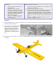
. The FOUR-STAR 40 is a fun aircraft to fly, but it is not a basic trainer. If you have no previous R/C flying experience, we suggest that you not attempt to fly this model without the assistance of an experienced pilot. Contact your local club or ask your hobby dealer for the names of good fliers in your area and a suitable location for flying. Practice taxiing the model while holding "up" elevator to avoid nose-overs. When you are ready for takeoff, point it into the wind and apply throttle.
. If you have any technical questions or comments about this kit, or any other SIG product, please call us. SIG MODELER'S HOTLINE 1-800-524-7805 Weekdays, 7:00am - 4.30pm Central © Copyright SIG Mfg. Co., Inc. SIG MFG. CO., INC............Montezuma, Iowa 50171-0520 LIMIT OF LIABILITY: In use of our products, Sig Mfg Co.'s only obligation shall be to replace such quantity of the product proven to be defective.