
User Manual

.
90.
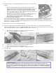
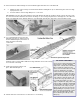
Shape the front of part FF so that the
plastic turtle deck will fit over it.
91.
Pin FF in place and mark the contour on
the front where it contacts the plastic
turtle deck.
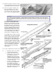
92.
Carve and sand FF to a streamline
shape.
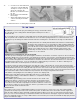
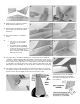
93.
a. Cut a 1/8" x 1-1/8" slot in the
fuselage to pass the rudder
pushrod.
b. The picture shows a Goldberg
small pushrod exit guide being
used to line the slot. However, the
slot can be coated with epoxy
glue to harden it and an exit guide
will not be necessary.
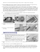
94.
The control horns should be installed before covering, then removed until the
covering is completed. Models with silk and dope covering have a hard enough
"shell" on the wood so that plywood reinforcement of the control horn area has not
been found necessary. Other types of covering call for reinforcement by insetting
a scrap plywood "scab" into the surface on the opposite side from the horn. This
will keep the horn from pulling out of the wood when subjected to unusual strain.
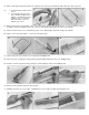
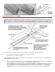
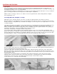
95.
The elevator pushrod exits through the opening in the fuselage rear end. Take
note that the elevator horn mounting holes are not centered on the elevator, but
must be offset to the side slightly to have the horn arm in the center.
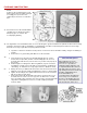
Cut the wheel cover from .030 ABS
Sheet Plastic and glue to the landing
gear with Celastic dipped in Acetone or
Dope Thinner.