The Kougar was designed as an advanced aileron trainer for fliers who have had some flying time on an intermediate trainer such as the Sig Komander or Sig Kavalier. While it is very maneuverable and can do difficult FAI pattern maneuvers and even accomplish lomcevaks, the model has been carefully tailored to handle easily and not be touchy in the hands of novice fliers. A fully symmetrical wing section provides good inverted and outside stunting characteristics. For use as a trainer, a .40 cu. in.
. About The Building Sequence The quickest and most efficient way to complete a model is to work on several pieces at the same time. While the glue is drying on one section you can start on or proceed with another part. We occasionally get suggestions that our instruction books should be in exact step-by-step building sequence. But this would result in many sentences starting "While the glue is drying on the fuselage, move to the wing etc.
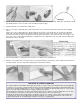
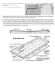
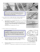
. 4. Lay the sheets flat. Scrape off the excess glue with a squeegee made from a balsa scrap. Finish glue cleanup with a damp rag. Weight down the sheets on a flat surface and allow to dry thoroughly. 5. Sand the wing skins smooth with the sanding block. 6. Cut one 7-sheet piece diagonally in two, with untaped side up, as shown by the dotted line marked "A" in the diagram below.
. 9. a. Sig Core Bond is recommended for applying the wing skins. This is a CAUTION special adhesive, light and strong, that is ideal for use with foam. As experienced modelers have found, many foam wing glues contain very Use only Sig Core Bond, Sig Kwikvolatile solvents. When using these glues, if the wing skin is put on before Set, Sig Epoxy Glue or Sig-Bond Glue the glue is absolutely dry, the still evaporating solvents are trapped in the on the foam wing cores.
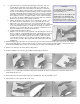
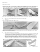
. 16. Repeat Step 11. 17. Repeat Steps 12 and 13. 18. Trim and sand the edges of the sheeted foam cores. While the regular sanding block can be used, note how useful an extra long block is for this purpose. (The one shown is made from a section of aluminum channel extrusion - with sandpaper glued on using sanding disc adhesive. This handy specialized glue is available at hardware stores and lumber yards. 19. Glue on the 1/4"x3/4" leading edge, holding it in place with pins and strips of masking tape.
. 24. Position the landing gear and drill a 5/32" diameter hole into the gear block and anchor block. CAREFUL! It is easy to slip and go clear through the wing. Trim the edge of the hole so that the radius of the wire at the bend will fit down into it. The gear should fit into the block snugly, but not tightly that it will jam in the block. You may want to remove it later for straightening after a hard landing. Place a nylon landing gear stra held on by No.
. Notes On Loops A true wing will perform perfect loops. A twisted wing will loop obliquely. One wing half being heavier than the other may also affect loop tracking. Side mounted motor may make one side of the model heavier than the other. Put weight in opposite wing tip until balanced. Should your model snap roll out of the top of a loop, it may snap in the direction of any twist in the wing, but the real reason for it snapping is because of a stall.
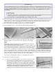
. INSTALLING EASY HINGES Using a No.11 X-Acto blade (or similar) cut a slot approximately 1/2" in depth and slightly wider than the hinge. After all slots have been cut, insert an Easy Hinge halfway into each slot in one of the pieces to be hinged. Then carefully slide the matching model part onto the other half of the hinges. You'll find it easiest to slide the part onto the hinges at an angle, one hinge at a time. At this point the surface to be hinged is attached but not glued.
. NOTE: If you are in a hurry to get the model built and aren't interested in a perfect bottom line contour between the wing and fuselage, ignore Steps 35 and 36. Look ahead to Step 37 for an explanation of a simplified wing bolt hole reinforcement. 35. Cut out inserts for the 1/16" plywood PB squares and drill 1/4" diameter holes through them from the other side of the wing. Epoxy glue PB in place. 36. a.
. 40. Carve the blocks roughly to shape so that the contour of the fuselage bottom block is carried on to the wing. 41. 42. a. Glue the blocks to the wing and fine sand the shape as shown. b. Fill any small remaining gaps with Sig Epoxolite or a mixture of Sig Kwik-Set glue and micro-balloons or talcum powder. a. Cut a cavity in the wing for the servo. Size will depend on the servo and/or mount. Look ahead in the book for further ideas on the requirements for this hole. b.
. FUSELAGE CONSTRUCTION NOTE: Vertical or side mounting may be used, but the tank position should be changed accordingly to keep it in the same relationship to the motor's needle valve hole. 47. Smooth and even F-IA and F-IB with the sandpaper block. Glue them together with epoxy glue, as shown in the accompanying drawing. 48.
. 51. (NOTE: The photo shows the Kavalier firewall, but the process is the same for the Kougar.) a. Bolt the spinner backplate to the motor. (This must be done to allow for differences in spinners. For example, the Goldberg spinner has a recessed backplate which requires the motor to be farther forward than a spinner without a recess. This is a good thing, giving more clearance behind the motor for fuel lines, and is one reason - other than the pleasing shape - that we recommend the Goldberg for the Kougar.
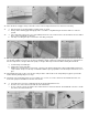
. 58. Mark the locations of Formers F-2 and F-3 on the triangular stock because the doubler will cover up the location lines. 59. Fit the die-cut plywood doublers into place. Sand wherever necessary to make them sit in the proper location. Leave the black line of the wing saddle area --- don't cover it with the doubler. CAUTION Do not glue the plywood doublers, on with Sig Bond, Tite Bond, Elmer's white glue or any other adhesive that has a water base.
. 62. Notch out the plywood doubler and side as required to pass the motor mount blind nut later when the sides are joined. 63. a. Using the pattern, drill 1/4" holes in F-2. b. Check the dowels in the holes. They should fit snugly but not so tight as to be difficult to remove. Sand the holes as required to make the dowels come out without a lot of force. 64. At this point check the top view plan of the rear of the fuselage and look ahead to picture No. 71.
. 72. Saw a notch in the bottom triangle stock, flush with the plywood doubler to accomodate F-IB. 73. a. Sand the bottom of the fuselage smooth and level with the sanding block. (As is shown being done to the fuselage top in picture No. 79.) b. Cover the bottom of the fuselage with pieces of 1/8" sheet. IMPORTANT! Leave the sides pinned down to the board until after the bottom sheeting is glued on and is dry.
. 77. a. Cover the holes in the blind nuts on the back of the firewall with small pieces of tape to prevent glue from oozing into the threads. (Look ahead to Picture No. 80.) b. Epoxy the block and firewall to the fuselage. c. Shape and sand the block to the contour formed by the firewall and F-2. Assemble the tank for use during Steps 78 and 79. TIPS ON TANKS IMPORTANT: To prevent fuel spray from staining the canopy, run the tank vent line out of the bottom of the cowling.
. NOTE: Photos 78 and 79 show the Kavalier fuselage, but the procedure is exactly the same for the Kougar. 78. Practice installing the tank to make sure that it can easily be passed from the radio compartment of through the tank cap hole in the firewall. Modify anything that interferes with easy placement and removal of the tank. 79. Glue scrap blocks on each side of the tank and at the rear end to hold it in position. Don't get the blocks too tight, just enough to keep the tank from rattling around.
. REAR DECK AND TAIL ASSEMBLY Note: The stabilizer and rudder parts are easiest to cover before they are hinged and attached to the fuselage. Refer to the Finishing section and prepare the tail parts before hinging and attaching to the fuselage. Test assemble them on the hinges before covering to insure that a good edge and end match has been obtained in the sanding operation. 87. Saw out the tail parts. Fit them together, using the sanding block. Glue and pin down the wax paper. 88. a.
. 90. Shape the front of part FF so that the plastic turtle deck will fit over it. 91. Pin FF in place and mark the contour on the front where it contacts the plastic turtle deck. 92. Carve and sand FF to a streamline shape. 93. a. Cut a 1/8" x 1-1/8" slot in the fuselage to pass the rudder pushrod. b. The picture shows a Goldberg small pushrod exit guide being used to line the slot. However, the slot can be coated with epoxy glue to harden it and an exit guide will not be necessary. 94.
. COVERING AND FINISHING IMPORTANT: Don't skip covering the fuselage and tail just because they are solid wood. Painting them without covering first is not enough. They will be much more resistant to splitting and breaking on hard impacts if they are covered with something - Sig Silk, Silkspan, Sig Silray or iron-on covering material. The manufacturer's directions for applying iron-on coverings are packed with the material.
. . Allow the water to dry out of the wood before applying the first full coat of clear dope. Apply 3 or more coats of clear dope. Sand with 220 3M Tri-M-Ite or other no-load paper. Keep in mind that extra coats of dope will add weight. Sig Lite Coat clear dope may be used in place of Supercoat Clear if desired. It has low shrink characteristics and is less likely to warp. Three coats of clear should provide a good base for color. Sand lightly when dry with 220 grit 3-M Tri-M-Ite no-load paper.
. 96. Stik-Tite Water-Slide Cut out the decals with a pair of sharp scissors. Leave 1/32" to 1/16" of clear edge around the decal. Round corners when cutting. Wet the surface on which the decal will be placed with soapy water (dishwater detergent). Place the decal on the model and squeegee the water from underneath with a balsa paddle. Allow to dry. This procedure will prevent air from being trapped underneath as is possible when the decals are applied dry.
. NOSE GEAR 97. a. The nose gear is held in the nylon bearing by the steering arm. Angle the arm forward so that when the servo pulls it back for a left turn, the arm will clear the face of the firewall. b. A flexible steel cable pushrod with nylon outer tubing (not furnished) is recommended for the hookup of the nose gear, such as the SIGSH559 Flexible Cable Pushrod. Run the nylon outer tubing through the firewall at the right spot to connect the inner cable to the nylon steering arm.
. You should decide on which type of fittings you will use in the case of the cable pushrods and have them on hand during fitting construction because the type chosen will affect the location of the pushrod exit holes through the firewall, etc. The balsa pushrods to the rudder and elevator are not limited as to location and can be adapted to any of the types of connectors shown without preliminary planning of exact position.
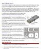
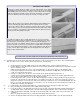
. Radio installation in one of the prototype Kougars A UM-3 plastic mount on the 3/8" sq. crosspieces holds three EK-MM servos. The receiver is wrapped in a foam rubber package and stowed just ahead of the servos. Some RC outfits have one or more reverse direction servos which are handy when it is found more convenient in a particular installation to have a pushrod hook to the servo on the opposite side.
. WHY MODELS MUST BE INDIVIDUALLY BALANCED Balancing The recommended Center of Gravity locations are: Test Fly with the balance point located anywhere between the leading edge at the wing tip and 1/2" back from the leading edge at the wing tip. Sport Fly at 1/2" back from the Leading Edge at the wing tip. Aerobatics - If your model will spin in both directions at 1/2" it need not be moved back any further. Some models need the balance point at 3/4" back for full response.
. FLYING IMPORTANT: The Kougar is not a basic trainer. If you have no previous RC flying experience you cannot successfully fly a fast and responsive design like the Kougar, particularly on test flights. It is suggested that you not attempt flying without the assistance of a modeler with experience. Contact your local model club or ask your hobby dealer for the names of good fliers in your vicinity and a suitable location for flying.
.
.
.
.
.
.
.
. © Copyright SIG Mfg. Co., Inc. SIG MFG. CO., INC. Montezuma, Iowa 50171-0520 LIMIT OF LIABILITY: In use of our products, Sig Mfg. Co.'s only obligation shall be to replace such quantity of the product proven to be defective. User shall determine the suitability of the product for his or her intended use and shall assume all risk and liability in connection therewith.