
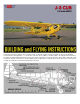
PIPER J-3 CUB Kit Manual

.
N.
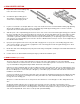
Add the balsa blocks on each side of the plywood cross
-plate and sand to match the shape of the wing.
O.
By pushing a pin through the wing, locate the exact spot for the wing hold down bolts in the centers of the hardwood
triangles at the back corners of the cabin. Drill through the wing and on through the hardwood blocks with a number 7 drill.
Remove the wing. Drill out the hole in the wing to 1/4" diameter to pass the 1/4
-
20 nylon wing hold
-
down screws.
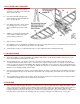
P.
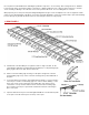
Prepare the firewall for installation by installing the blind nuts that retain the motor mounts and epoxying in place. Select and
position the fuel tank while easy access is available to the inside of the fuselage nose.
(NOTE: The tank level depends on the motor installation. The center line of the tank should be about 3/8" below the needle
valve. An inverted engine will therefore require a lower tank than when the engine is side mounted. The plan shows use of
an inverted engine with low tank position to provide full space on both sides of the cowl for installation of a super-detailed
dummy engine. For sport flying or stand-off scale events, a side mounted engine is more practical however, since the idle
adjustment is less critical and the engine is easier to work on and start. Since the engine cylinders on the actual airplane are
exposed, the model engine in the side-
mounted position doesn't look unrealistic. The tank location for a side mounted engine
requires that the top fuselage cross pieces in the nose be removed and a cut out made into the front fuselage formers F-1
and F-2 to get the tank in a high enough position. Plank the top of the fuselage nose with 3/32" balsa sheeting before
removing the cross pieces and cutting into the formers to accomodate the tank. A super-detailed model with an instrument
panel will need a specially selected tank shape because most standard plastic bottle clunk tanks are too long to fit in front of
it.)
Q.
Drill holes through the firewall to pass the tank tubes.
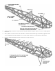
R.
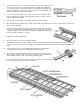
Plank the sides of the front fuselage forward of the split line with 3/32" sheet balsa. If the top of the front fuselage has not
already been planked as described previously during installation of a side-mounted engine tank, it may be covered now.
Wetting the balsa sheet will enable it to be bent around the curvature of the fuselage top.
S.
Add the balsa block bottom to the nose section.
T.
Inset 3/32" sheet balsa cabin floor between the bottom 1/4" square longerons.
U.
Epoxy the 1/8" plywood firewall to the front of the fuselage.
V.
Glue on F
-
1, F
-
2 and F
-
4 through F
-
7.
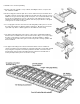
W.
Install the fin
-
elevator mounting blocks. Epoxy 1/4" dowels into holes. Measure from plans for accuracy.
X.
Glue the side and top stringers in place. The top stringers may have to be soaked in water or steamed near the cabin so that
they may be curved into place. Note that the center top stringer is actually two 1/8" square pieces, the first glued into the
notches in the formers and the second glued on top.
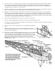
7. LANDING GEAR
The landing gear is most easily assembled by first fastening the front and rear 1/8" and 3/32" formed wires into the
grooved landing gear blocks with the nylon strap and screws provided. Bind the 1/16" formed wires in place with fine
copper wire (not furnished) such as Sig Copper Wire SH330. Some slight rebending of individual wires may be necessary
to get an exact fit When the gear is lined up properly, solder all of the copper wired connections together.
Three-inch balloon type wheels are recommended for best scale appearance. To use Banner Streamlite wheels which
have a scale-like hub, solder a piece of 1/8" I.D., 5/32"O.D brass tubing over the axle. Use this type of bushing for any
type of wheel which has a predrilled 5/32" hole.
8. COWLING
Notes before starting: The cowling should be assembled and fitted to the fuselage
before the fuselage is covered and painted. Careful shaping of the nose is
necessary to achieve a good fit. Butyrate dope thinner, MEK, or cyanoacrylate
adhesives can be used to assemble the cowl. The most common cause of plastic
cowls cracking is distortion of the plastic from improper installation of the plywood
mounting inserts and retaining screws. If the plastic is fully supported by the
plywood underneath, no strain will occur when the screws are tightened down.
Keep this in mind while working through this section of the instructions.