
PIPER J-3 CUB Kit Manual

.
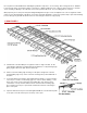
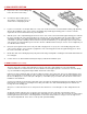
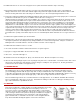
4. ELEVATOR AND STABILIZER
A.
Laminate two S-1 pieces to make a
single piece 1/4" thick. Do the same with
pieces S-2 through S-6.
B.
Protect the plan with wax paper. Pin
down and glue together with Sig Bond,
pieces S-1 through S-6.
C.
Note that the two halves of the elevator
are joined by a piece of 1/4" dowel
which is built into the structure at this
time.
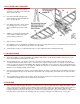
D.
Add the 1/4" square balsa trailing edge
of the stabilixer, leading edge of the
elevator and the end pieces.
E.
Ribs are 2/32" x 1/4" balsa.
F.
The stabilizer is not covered until after installation on to the two fuselage dowels. There is a gap between the fuselage and
the satbilizer frame to simulate the same effect in the real airplane.
G.
Sand all edges round. Do not airfoil the tail surfaces as the original was made of tubing and was flat.
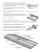
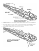
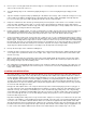
5. FIN AND RUDDER
A.
The fin and rudder are constructed similar to the stabilizer and elevator, except that the outline is formed of 1/4" x 1/2"
balsa sticks rather than laminated die cut shapes.
B.
The plan duplicates the scale structure of the fin on the full size Cub and thus has no rib at the bottom of the fin. The
covering is stretched from the lower 3/32" x 1/4" rib to the 3/16" square fuselage stringers on each side to provide a fillet
effect. If you are not experienced at handling silk in this type of application or are using some other covering material, it is
recommended that another piece of 1/4" square be added to the structure as shown in the accompanying detail so that the
fin may be covered independently of the fuselage.
C.
The fin is incorporated into the structure of the fuselage during its assembly, so take this into account during construction.
Note particularly that the fin post extends down to the bottom of the fuselage and is notched into the rear of the fuselage
frame.
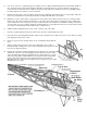
D.
The fin leading edge extends into the fuselage. The fin must be mounted on the fuselage before the top stringers and the
1/4" stabilizer mounting dowels and associated blocks are installed.
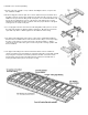
6. FUSELAGE
A.
Protect the plans with wax paper. Pin down 1/4" square pieces to form a fuselage side frame, gluing with Sig Bond. Each
side is composed of two separate sections, with the split occuring at the double 1/4" square located at Former 2. This is to
permit incorporation of the taper toward the nose when the sides are joined together. Note that the right side of the
fuselage is different from the left side. If you wish to install an operating cabin door. If you do not intend to use this feature,
both sides may be made like the left side, without the door opening, and may be assembled on top of each other.