
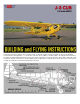
PIPER J-3 CUB Kit Manual

.
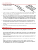
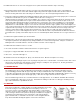
2. WING CENTER SECTION
A.
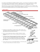
Prepare the center section trailing edge
in the same maner as the wing.
B.
Assemble the plywood wing joiners.
Then add 1/4" square balsa pieces as
shown in the accompanying sketch.
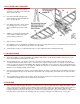
C.
Lay the four center ribs over the plan with 1/16" scrap scabs under the fronts to level them with the trailing edge planking.
Glue the two middle ribs of the center section to the trailing edge and the plywood wing joiners. Leave the outer ribs
unglued for the moment and hold them in position with pins.
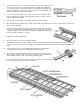
D.
Slide the spars of the completed wing panels into the holes of the center section ribs and the plywood wing joiner ends into
the holes of the W-2 ribs of the wing panel. Block up each tip 7/16", measured at rib W-4. This procedure will necessitate
enlarging the bottoms of the plywood wing joiner holes in the W-2 ribs and the bottoms of the spar holes in the center
section ribs to permit the swiveling action needed to incorporate the dihedral. If you are planning to fly the Cub by rudder
only control it is recommended that you increase the amount of dihedral under each tip to one inch. For free flight Cub, put
2" of dihedral under each tip.
E.
Epoxy the spars together and re-inforce the joints with scrap plywood. Use epoxy also on the trailing edge joints to the
center section. Glue the outer center ribs up against the ends of the wing panels and to the plywood wing joiners. Sheet
the center section with 1/16" balsa.
F.
Fill all dents and cracks with Sig Epoxolite putty. Sand entire wing carefully with a sanding block and finish with hand-held
fine sandpaper.
G.
Control surfaces are attached with molded nylon hinges provided in the hardware pack.
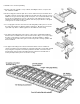
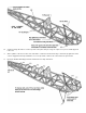
3. WING STRUTS
(See Plan)
The front strut for the J-3 Cub is approximately 21" long.The rear strut is approximately 21-1/2" long. Individual
construction differences between models can cause variations in the lengths required, so measure for exact size directly
on your model with the wing permanently installed. Sand strut to airfoil shape.
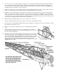
Drill two holes in the aluminum shim stock where it will be inside the spruce wing strut. These holes will enable the epoxy
glue to get a good grip on the aluminum. Cut a slot in the end of the strut with a razor saw, and epoxy the aluminum strip
into the slot. Wrap a piece of fine cloth (silk or fiberglass), coated with epoxy, around the end of the strut to reinforce the
installation of the aluminum.
Screws are provided to fasten the upper wing strut ends to the plywood strut attachment plates that are built into the wing.
Bolt and nuts are provided for connecting the lower wing strut ends to the shim aluminum fittings that are built into the
fuselage above the landing gear.
Glue piece of 1/16"x1/8" balsa to the "U" shaped 1/16" wire strut braces. Cover with paper or silk to firmly attach to the
wire.
An alternate popular method for the construction of the strut ends is shown on the plan. The materials for these
modifications are not furnished in the kit. Molded nylon pinned hinges are shown for the upper strut ends to enable them to
fold flat against the bottom surface of the wing when it is removed for transportation or storage. For the fuselage end of
each strut an adjustable RC clevis can be used to provide quick detachability.