This model of the famous Piper Cub is a natural for radio control, but can also be flown free flight - an increase in dihedral is recommended for this application - or converted to control line by the addition of leadout guides to the wing tip and a bellcrank in the cabin. The stable flight characteristics make it a good RC scale trainer for inexperienced fliers, but it can be stunted by expert expert pilots.
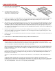
. Die-cut parts are marked with letters indicating the particular component - "F" for fuselage, "W" for wing and "S" for stabilizer. Leave the parts in the sheet until needed for construction so that they will not be lost or broken. Remove the pieces from the sheets carefully. If difficulty is encounted, do not force the part from the sheet. Use a modeling knife to cut it free.
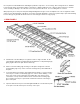
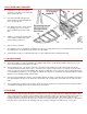
. E. Thread the wing ribs over the spars. If any of the spar holes are too tight, do not try to force the rib onto the spar but enlarge the hole slightly so that it will slip over the spar easily. For spars which may have a natural bow, the height of the spar holes should be increased so that the spar can be accomodated in the rib with the rib sitting flat on the building surface. F. Use 1/16" scrap balsa scabs under each rib, front and rear, on the flat bottom before the upward curve starts.
. P. Add the 1/16" sheet front planking. Q. Put the 1/16"x1/8" capstrips on top of all ribs, including the aileron, except for the two end W-2s and W-5. R. Remove wing panel from the plan. The 1/8"x1/4" bottom front spar should be inset into W-8 as was the top front spar. Install gussets made from die cut sheet scrap. In addition to the gussets in the wing shown on the plan, it is recommended that scrap gussets also be added to the corners of the ailerons.
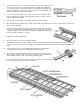
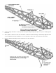
. 2. WING CENTER SECTION A. Prepare the center section trailing edge in the same maner as the wing. B. Assemble the plywood wing joiners. Then add 1/4" square balsa pieces as shown in the accompanying sketch. C. Lay the four center ribs over the plan with 1/16" scrap scabs under the fronts to level them with the trailing edge planking. Glue the two middle ribs of the center section to the trailing edge and the plywood wing joiners.
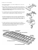
. 4. ELEVATOR AND STABILIZER A. Laminate two S-1 pieces to make a single piece 1/4" thick. Do the same with pieces S-2 through S-6. B. Protect the plan with wax paper. Pin down and glue together with Sig Bond, pieces S-1 through S-6. C. Note that the two halves of the elevator are joined by a piece of 1/4" dowel which is built into the structure at this time. D. Add the 1/4" square balsa trailing edge of the stabilixer, leading edge of the elevator and the end pieces. E.
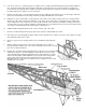
. B. Set the fuselage side frames over the top view on the plans and join, using 1/4" square cross pieces and the plywood former F-3. C. At the split line of the front section of the side frames, sand a bevel in the back edge so that it fits up against the other section snugly when the taper toward the nose is incorporated. Join the front sections with 1/4" square balsa. D. Epoxy the hardwood landing gear blocks between the fuselage side frames.
. E. Cut out 1/8" of the 1/4" sq. bottom longerons and glue on the 1/8" plywood tail wheel bracket mount. Bend the tail wheel wire, insert through the nylon tail wheel bracket. Bend the steering arm in the top. Screw the bracket to the plywood mount. Hook the steering arm to the rudder by epoxying a metal strap into the rudder. Do not fit the strap tightly against the arm but allow some clearance for free movement. F.
. N. Add the balsa blocks on each side of the plywood cross-plate and sand to match the shape of the wing. O. By pushing a pin through the wing, locate the exact spot for the wing hold down bolts in the centers of the hardwood triangles at the back corners of the cabin. Drill through the wing and on through the hardwood blocks with a number 7 drill. Remove the wing. Drill out the hole in the wing to 1/4" diameter to pass the 1/4-20 nylon wing hold-down screws. P.
. A. Recess a piece of 3/32" plywood into the 3/32" fuselage nose sheeting in the area shown on the plan under the cowl sides. Do this on both sides of the nose. B. Tru-up the mating edges of the cowl halves by lightly moving across a sheet of 80 grit garnet paper laying on a flat surface. C. Tape the cowl halves together and try a preliminary fit of the match to the fuselage. If the cowl fits the fuselage too loosely, remove a little more width by sanding down the seam between the two halves again.
. The mist coat of clear forms a barrier between the wet, heavy coat of clear and the trim colors, so that the heavy coat of clear will not soften the trim colors and cause them to bleed and run. "DKM" STIK-TITE PRESSURE SENSITIVE DECALS Cut out the decals with a pair of sharp scissors. Leave about 1/32" to 1/16" of clear edge around the decal. Round the corners as you are cutting. Wet the surface on which the decal will be placed with soapy water (use dishwasher detergent).
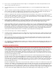
. The drawing shows a convenient way to make a "Z" bend in the end of a wire for easy connection of a pushrod or R/C link to a nylon bellcrank. The pushrod may be threaded through the ribs before the bellcrank is bolted in place. Soldered connections to the bellcrank are not recommended because the nylon can be damaged by the heat of the iron. The pushrods for the fuselage are pieces of firm 1/4" square balsa. The 1/16" wire ends are wrapped with thread and coated with glue.
. 13. FLYING If you are a newcomer to model flying it is suggested that you not attempt flying without the assistance of a modeler with experience. Contact your local model club or ask your hobby dealer for the names of good fliers in your vicinity and a suitable location for flying. Many hours of work are involved in the construction of a model and it can all be lost in a moment of beginner's indecision.
.
. © Copyright SIG Mfg. Co., Inc. SIG MFG. CO., INC............Montezuma, Iowa 50171-0520 LIMIT OF LIABILITY: In use of our products, Sig Mfg. Co.'s only obligation shall be to replace such quantity of the product proven to be defective. User shall determine the suitability of the product for his or her intended use and shall assume all risk and liability in connection therewith.