OWNER´S MANUAL INSTRUCTIONS- INSTALLATION-OPERATION-MAINTENANCE OVENS AND MULTIPLES SR-4-24, SR-6-36, SR-24G -24, SR-36G -36, SR-4B-12G-36, SR-2B-24G-36 **READ THIS MANUAL IN IT’S ENTIRELY BEFORE USING THIS RANGE** 5659 ROYALMOUNT AVE MONTREAL, QC, CANADA H4P 2P9 TEL (514) 737-9701; 1-888-275-4538
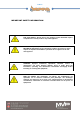
to 17 IMPORTANT SAFETY INFORMATION FOR YOUR SAFETY: Do not store or use gasoline or other flammable vapors or liquids in the vicinity of this or any other appliance. MESURE DE SÉCURITÉ: Ne pas entreponer ni utiliser d´essence ni autres vapeurs ou liquides inflammables á proximité de cet appareil ou de tout autre appareil. WARNING: Improper installation, adjustment, alteration, service or maintenance can cause property damage, injury or death.
to 17 PLEASE RETAIN THIS MANUAL FOR FUTURE REFERENCE All equipment manufactured by SIERRA RANGE. is for use with the type of gas specified on the rating plate and for installation will be in accordance with National Fuel Gas Code ANSI Z223.1 (latest edition) IMPORTANT: Installing, Operating and Service Personnel: Qualified, certified licensed and/ or authorized personnel who are familiar with and experience in state/local installation codes should perform installation of the equipment.
to 17 Provisions shall be incorporated in the design of the kitchen, to ensure adequate supply of fresh air and adequate clearance for air openings into the combustion chamber, for proper combustion, and ventilation. For proper operation of the appliance, do not obstruct the flow of combustion and ventilation air. The installation must conform with local codes, or in the absence of local codes, to the national fuel gas code, ANSI Z223.1 (or latest addenda).
to 17 All Sierra appliances are adjusted and tested before leaving the factory, effectively matching them to sea level conditions. Adjustments and calibrations to assure proper operation may be necessary on installation to meet local conditions; low gas characteristics, to correct possible problems caused by rough handling or vibration during shipment, and are to be performed only by qualified service personnel.
to 17 movable appliances, there is a restraining device at the rear of the unit. If disconnection of the restraint is necessary, reconnect the restraint after the appliance has been returned to its originally installed position. CLEANING DAILY: Clean top grate(s) with warm water, mild cleaner and wire brush. Clean and brush off debris from and around the burner area. Empty and clean grease pan.
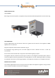
to 17 INSTALLATION OF LEGS LEGS ASSEMBLY: Mount Legs on bottom of product, the appliance may be further leveled with adjustment in the foot of the leg. GAS CONNECTION The gas supply (service) line must be the same size or greater than the inlet line of the appliance. SIERRA appliances use a ¾” NPT inlet. Pipe joint compound must be resistive to Natural or LP gas. For equipment using propane gas do not install supply lines with a diameter less than ½ under any circumstances.
to 17 LOCATION • Installation of the equipment should be performed by qualified, certified, and authorized personnel who are familiar and experienced with local installation codes. • Before Installation please read instructions completely and carefully. • Do not remove permanently affixed labels, warnings or plates from the product. • Please observe all local and national codes and ordinances • In U.S.
to 17 Air movement should be checked during installation. Air openings or baffles may have to be provided in the room, if pilot or burner outage problem persists. RATING PLATE Information on this plate includes the model, serial number, BTU / hour input of the burners operating gas pressure in inches WC, and whether the appliance is orifices for natural or propane gas.
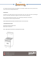
to 17 BACK-SPLASH INSTALLATION Identify the assemblies to be fitted over the equipment. Make sure you have all the tools and fasteners listed.
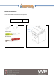
to 17 Remove the 3 rear screws of the unit.
to 17 Place and tight the hex screws in the shown positions. SHELF INSTALLATION Place the shelf over the backsplash and hook it on the very top of it.
to 17 Fit the M6 screws on the inside of the shelf to secure it in position.
to 17 Door installation STEP 1.- Place the assembler component in both hinges (you can find 2 pieces of it in carton legs box ) STEP 2.-Hold onto both hinges with your hands. STEP 3.- Raise the door until the door is at a 45 degrees angle. STEP 4.-Pull the door towards you and lift up. To put the door back in, reverse these instructions.
to 17 TROUBLESHOOTING BURNER AND/OR PILOTS NOT TURN ON UNIT PRODUCING CARBON DEPOSITS PILOT WILL NOT REMAIN LIT EXCESSIVE FLARE-UP NOT HEATING PROPERLY GAS SUPPLY TO COOKING EQUIPMENT IS OFF GAS TYPE GAS SUPPLY PRESURE PRIMARY AIR NOT ADJUSTED PROPERLY ORIFICE TOO BIG PILOT FLAME NOT ADJUSTED DRAFT CURRENTS NEAR EQUIPMENT NOT ENOUGH VENTILATION DEBRIS OR GREASE CLOGGING PILOT BURNER TURN ON GAS SUPPLY OVERLOAD OF OIL AND LEFTOVERS ORIFICES DIRTY/CLOGGED CLEAN AND PREPARE PAN LOW GAS PRESSURE GRA
to 17 LIMITED WARRANTY MVP Group Corp.
to 17 (514) 737-9701 (888) 275-4538 service@mvpgroupcorp.com 5659 Royalmount Ave Montreal, QC, Canada H4P 2P9 (786) 600-4687 (844) 218-8477 service@mvpgroupcorp.