
Specifications


Product Technical Specification & Customer Design Guidelines
86 Proprietary and Confidential - Contents subject to change 4114634
GNSS RF receive path test
The GNSS receive path uses the dedicated GNSS connector.
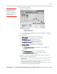
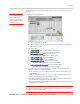
To test the GNSS receive path:
1. Inject a carrier signal at -110dBm, frequency 1575.52 MHz into the GNSS Rx
path at the connector. (Note that this frequency is 100 kHz higher than the
actual GPS L1 center frequency.)
2. Test the signal carrier-to-noise level at the GNSS receiver:
a.
AT!ENTERCND (Unlock extended AT command set.)
b.
AT!DAFTMACT (Put modem into factory test mode.)
c.
AT!DACGPSTESTMODE=1 (Start CGPS diagnostic task.)
d.
AT!DACGPSSTANDALONE=1 (Enter standalone RF mode.)
e.
AT!DACGPSMASKON (Enable log mask.)
f.
AT!DACGPSCTON (Return signal-to-noise and frequency measurements.)
g. Repeat
AT!DACGPSCTON five to ten times to ensure the measurements
are repeatable and stable.
3. Leave the RF connection to the Mini Card device intact, and turn off the
signal generator.
4. Take several more
!DACGPSCTON readings. This will demonstrate a 'bad'
signal in order to set limits for testing, if needed. This frequency offset should
fall outside of the guidelines in the note below, which indicates that the CtoN
result is invalid.
5. (Optional) Turn the signal generator on again, and reduce the level to -
120dBm. Take more
!DACGPSCTON readings and use these as a reference
for what a marginal/poor signal would be.
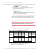
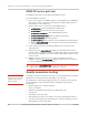
Note: The response to AT!DACGPSCTON for a good connection should show CtoN within
58 +/- 5dB and Freq (frequency offset) within 100000 Hz +/- 5000 Hz .
Quality assurance testing
Note: QA is an ongoing
process based on random
samples from a finished
batch of devices.
The quality assurance tests that you perform on your finished products should be
designed to verify the performance and quality of your devices.
The following are some testing suggestions that can confirm that the antenna is
interfaced properly, and that the RF module is calibrated and performs to
specifications:
• Module registration on cellular networks
• Power consumption
• Originate and terminate data and voice (if applicable) calls
• Cell hand-off
• Transmitter and receiver tests
• FER (Frame Error Rate) as an indicator of receiver sensitivity/performance
• Channel and average power measurements to verify that the device is trans-
mitting within product specifications