
Specifications

Testing
Rev 8 Apr.14 Proprietary and Confidential - Contents subject to change 85
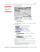
To test the DUT’s receive path (or diversity path, while connected to the diversity
antenna):
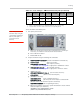
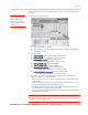
Note: This procedure
describes steps using the
Agilent 8648C signal
generator—the Rohde &
Schwarz SML03 is shown
for reference only.
1. Set up the signal generator:
a. Set the amplitude to -70 dBm
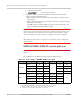
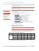
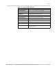
b. Set the frequency for the band being tested. See Table C-3 on page 84
for frequency values.
2. Set up the DUT:
a.
AT!ENTERCND (Unlock extended AT command set.)
b.
AT!DAFTMACT (Put modem into factory test mode.)
c.
AT!DASBAND=<band> (Set frequency band.)
· See Table C-3 on page 84 for <band> values
d.
AT!DALSTXBW=<bw> (Set Tx bandwidth.)
e.
AT!DALSRXBW=<bw> (Set Rx bandwidth.)
f.
AT!DASCHAN=<channel> (Set modem channel.)
· See Table C-3 on page 84 for <channel> values
g.
AT!DALGAVGAGC=<channel>,0 (Get averaged Rx AGC.)
· See Table C-3 on page 84 for <channel> values
3. Test limits—Run ten or more good DUTs through this test procedure to
obtain a nominal received power value.
· Apply a tolerance of
5 to 6 dB to each measurement (assuming a good
setup design).
· Make sure the measurement is made at a high enough level that it is not
influenced by DUT-generated and ambient noise.
· The Signal Generator power level can be adjusted and new limits found if
the radiated test needs greater signal strength.
· Monitor these limits during mass-production ramp-up to determine if further
adjustments are needed.
Note: The value measured from the DUT is significantly influenced by the test setup and
DUT design (host RF cabling loss, antenna efficiency and pattern, test antenna efficiency
and pattern, and choice of shield box).