
Specifications

Product Technical Specification & Customer Design Guidelines
84 Proprietary and Confidential - Contents subject to change 4114634
· Monitor these limits during mass-production ramp-up to determine if further
adjustments are needed.
Note: The value measured from the DUT is significantly influenced by the test setup and
DUT design (host RF cabling loss, antenna efficiency and pattern, test antenna efficiency
and pattern, and choice of shield box).
Note: Diversity is not
available in GSM mode.
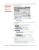
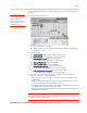
4. Test diversity paths:
a. Set up the signal generator as in Step 1.
Note: Setup of the DUT is
the same as in Step 2,
except for a change to
AT!DAWGAVGAGC and
the addition of
AT!DAWSSCHAIN.
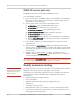
b. Set up the DUT:
i.
AT!ENTERCND (Unlock extended AT command set.)
ii.
AT!DAFTMACT (Put modem into factory test mode.)
iii.
AT!DASBAND=<band> (Set frequency band.)
· See Table C-2 on page 82 for <band> values
iv.
AT!DAWSSCHAIN=1 (Enable the secondary chain.)
v.
AT!DASCHAN=<channel> (Set modem channel)
· See Table C-2 on page 82 for <channel> values
vi.
AT!DASLNAGAIN=0 (Set the LNA to maximum gain.)
vii.
AT!DAWGAVGAGC=9400,0,1 (The ‘1’ indicates the diversity path is
used.)
c. Test the limits as in Step 3.
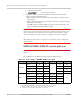
LTE RF receive path test
Note: This procedure segment is performed in Step 14 of the Production test procedure on
page 78.
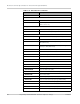
The suggested test procedure that follows uses the parameters in Ta bl e C -3
contains parameters used in the suggested test procedure that follows.
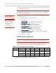
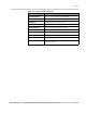
Table C-3: Test settings—LTE receive path
Mode Test category 800 MHz 900 MHz 1800 MHz 2100 MHz 2600 MHz
LTE
Band # B20 B8 B3 B1 B7
Frequency
a
(MHz) 806.00 942.50 1842.50 2140.00 2655.00
Band ID 56 47 44 34 35
Rx Channel
b
24300 21625 19575 18300 21100
a. Receive frequencies shown are 2 MHz offset from center
b. Channel values shown are at the center of the corresponding bands.