
Specifications

Product Technical Specification & Customer Design Guidelines
82 Proprietary and Confidential - Contents subject to change 4114634
i. Take the measurement.
j.
AT!DASTXOFF (Turn off the transmitter.)
3. Test limits—Run ten or more good DUTs through this test procedure to
obtain a nominal output power value.
· Apply a tolerance of
5 to 6 dB to each measurement (assuming a good
setup design).
· Monitor these limits during mass-production ramp-up to determine if further
adjustments are needed.
· For GSM mode, the transmit signal is bursted, so the transmit power will
appear averaged on the power meter reading.
Note: The module has a nominal output power of +23 dBm
1 dB in WCDMA mode.
However, the value measured by the power meter is significantly influenced (beyond the
stated
1 dB output power tolerance) by the test setup (host RF cabling loss, antenna
efficiency and pattern, test antenna efficiency and pattern, and choice of shield box).
Note: When doing the same test over the air in an RF chamber, values are likely to be
significantly lower.
UMTS (WCDMA/GSM) RF receive path test
Note: This procedure segment is performed in Step 14 of the Production test procedure on
page 78.
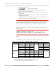
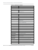
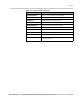
The suggested test procedure that follows uses the parameters in .
Table C-2: Test settings—WCDMA/GSM receive path
Mode Test category 850 MHz 900 MHz 1800 MHz 1900 MHz 2100 MHz
WCDMA
Band # B5 B8
n/a
B2 B1
Frequency
a
(MHz) 881.40 947.40 1960.00 2140.00
Band ID 22 29 15
b
9
Rx Channel
c
4182 2812 9400 9750
GSM
Band # GSM850 GSM900 DCS1800 PCS1900
n/a
Frequency
d
(MHz) 836.60 948.00 1842.20 1960.00
Band ID 18 10 11 12
Rx Channel
c
190 65 697 661
a. Receive frequencies shown are 1.2 MHz offset from center
b. Either 15 (WCDMA1900A) or 16 (WCDMA1900B) may be used for testing.
c. Channel values shown are at the center of the corresponding bands.
d. All values offset from actual center channel by +67 kHz