
Specifications

Testing
Rev 8 Apr.14 Proprietary and Confidential - Contents subject to change 81
To test the DUT’s transmitter path:
Note: This procedure
describes steps using the
"Power Meter: Gigatronics
8651A” (with Option 12
and Power Sensor
80701A).
1. Set up the power meter:
a. Make sure the meter has been given sufficient time to warm up, if
necessary, to enable it to take accurate measurements.
b. Zero-calibrate the meter.
c. Enable MAP mode.
2. Prepare the DUT using the following AT commands:
a.
AT!ENTERCND=”<password>”(Unlock extended AT command set.)
b.
AT!DAFTMACT (Enter test mode.)
c.
AT!DASBAND=<bandValue> (Set frequency band.)
· See Table C-1 on page 80 for appropriate <bandValue> values
d.
AT!DASCHAN=<channel> (Set modem channel)
· See Table C-1 on page 80 for appropriate <channel> values
e. (GSM mode only)
AT!DAGSTXFRAME=0, 1, 3000, 0 (Set Tx frame structure.)
f. AT!DASTXON (Turns on the transmit path.)
g. (WCDMA mode only)
AT!DAWSTXCW=0 (Use a modulated carrier.)
AT!DASPDM=2, 75 (Set the power level. Repeat command with
different offsets until desired Tx power is obtained.)
AT!DAWSPARANGE=3 (Set to high PA gain state.)
h. Offset the tracking (If necessary, repeat with different offsets until the
desired frequency is obtained.)
(WCDMA mode) AT!DASPDM=4,35100
(GSM mode) AT!DASPDM=0,2240
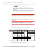
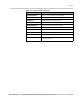
GSM
Band # GSM850 GSM900 DCS1800 PCS1900
n/a
Band ID 18 10 11 12
Tx
Channel
b
190 65 697 661
a. Either 15 (WCDMA1900A) or 16 (WCDMA1900B) may be used for testing.
b. Channel values shown are at the center of the corresponding bands.
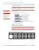
Table C-1: Test settings—UMTS transmission path (Continued)
Mode
Test
category
850 MHz 900 MHz 1800 MHz 1900 MHz 2100 MHz