
Specifications

Testing
Rev 8 Apr.14 Proprietary and Confidential - Contents subject to change 79
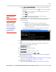
b. Select File > Connection Description. The Connection Description dialog
box appears.
i. Typ e Sierra in the Name box and click
OK. The Connect To dialog box
appears.
ii. Click
OK without changing any of the displayed information. The
Connect dialog box appears.
iii. Click
Cancel.
Note: If necessary, use
AT E1
to enable echo.
iv. Typ e ATZ in the HyperTerminal window. If the connection is
established, the message OK appears.
· Linux systems: Use a terminal emulation/communications program such
as minicom to connect over the device handle for AT commands (see
listings in Step 6):
Note: If the command
“minicom” is not found,
then use a different
program, or download
minicom and repeat this
step. See Downloading
and configuring minicom
for Linux systems on
page 80 for details.
i. Start minicom:
· First use of the modem: From the command line, type
minicom -s. (The ‘-s’ switch shows the configuration menu.)
· Subsequent uses: From the command line, type minicom. (The
‘-s’ switch is assumed.)
The minicom configuration details appear and the message OK
appears when the connection is established.
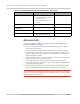
8. Display the firmware version:
·
ATI
9. Test the LED—Set the LED in blinking mode using this command, then
visually verify that the LED turns off and on:
·
AT!LDTEST=0,0 (LED on)
·
AT!LDTEST=0,1 (LED off)
10. Unlock the extended AT command set:
·
AT!ENTERCND
11. Put the module in diagnostic/factory test mode:
·
AT!DAFTMACT
12. Communicate with the SIM using +CPIN or +CIMI.
When performing RF tests, use a test platform as described in Suggested
testing equipment on page 87.
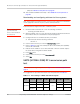
13. Test RF transmission, if desired:
· (UMTS) See UMTS (WCDMA/GSM) RF transmission path test on page 80.
· (LTE) To test the LTE transmission path, use a call box.
14. Test RF reception, if desired:
· (UMTS) See UMTS (WCDMA/GSM) RF receive path test on page 82.