
Specifications
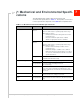


Mechanical and Environmental Specifications
Rev 8 Apr.14 Proprietary and Confidential - Contents subject to change 65
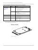
Specific areas requiring heat dissipation are shown in Figure 7-4:
• RF—Top and bottom faces of module near RF connectors. Likely to be the
hottest area.
• Baseband—Top and bottom faces of module, below the RF area.
To enhance heat dissipation:
• Maximize airflow over/around the module.
• Locate the module away from other hot components.
• Module mounting holes must be used to attach (ground) the device to the
main PCB ground or a metal chassis.
• You may need to add a heat sink that mounts the module to the main PCB
(thermal compound or pads must be used between the module and the heat
sink).
• You may also need active cooling to pull heat away from the module.
Note: Adequate dissipation of heat is necessary to ensure that the module functions
properly.
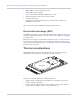
Module integration testing
When testing your integration design:
• Test to your worst case operating environment conditions (temperature and
voltage)
• Test using worst case operation (transmitter on 100% duty cycle, maximum
power)
• Monitor temperature at all shield locations. Attach thermocouples to the areas
indicated in Figure 7-4 on page 64 (Baseband, RF).
• Monitor the module’s internal temperature using the command
AT!PCTEMP.
(See [2] AirPrime MiniCard MC73xx/MC8805 AT Command Reference
(Doc# 4114486).)
Note: Make sure that your system design provides sufficient cooling for the module—
proper mounting, heat sinks, and active cooling may be required, depending on the
integrated application.
The internal module temperature must be kept to <100
°C when integrated to prevent
damage to the module’s components. For best performance, keep the internal module
temperature below 85°C.
(For acceptance, certification, quality, and production (including RF) test
suggestions, see Testing on page 75.)