
Specifications


Power
Rev 8 Apr.14 Proprietary and Confidential - Contents subject to change 55
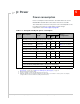
Figure 5-1: Voltage/temperature monitoring state machines
Power interface
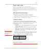
Power ramp-up
On initial power up, inrush current depends on the power supply rise time—turn
on time >100 µs is required for < 3A inrush current.
The supply voltage must remain within specified tolerances while this is occurring.
Power-up timing
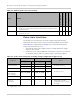
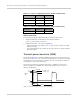
Figure 5-2 describes the timing sequence for powering the module on and off.
Figure 5-2: Signal timing (Power-on, and USB enumeration)
Off mode
Normal mode
Low power mode
Handled by Power
State state machine.
current_vcc > VOLT_LO_NORM
current_temp <= TEMP_HI_NORM
current_vcc < VOLT_LO_CRIT
current_temp > TEMP_HI_CRIT
current_vcc > VOLT_LO_NORM
current_temp < TEMP_HI_NORM
current_vcc < VOLT_LO_WARN
current_temp > TEMP_HI_WARN
current_vcc < VOLT_HI_NORM
current_temp > TEMP_NORM_LO
current_vcc > VOLT_HI_CRIT
current_temp < TEMP_LO_CRIT
Host cuts power to VCC line
Normal mode
Low supply voltage warning
or
High temperature warning
OFF
Power-on
Sequence
USB_D+
(Double enumeration)
OFF
Active
DEVICE STATE
High
Low
High
VCC
Low
t_pwr_on_seq
t_USB_active
t_USB_suspend
USB_D+
(Single enumeration)
High
Low
t_pwr_on_seq