
Specifications


Product Technical Specification & Customer Design Guidelines
54 Proprietary and Confidential - Contents subject to change 4114634
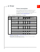
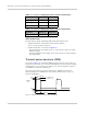
Power state transitions
The module uses state machines to monitor supply voltage and operating
temperature, and notifies the host when critical threshold limits are exceeded.
(See Table 5-5 for trigger details and Figure 5-1 for state machine behavior.)
Power state transitions may occur:
• Automatically, when critical supply voltage or module temperature trigger
levels are encountered.
• Under host control, using available AT commands in response to user choices
(for example, opting to switch to airplane mode) or operating conditions.
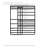
Sleep • Normal state of module between calls or data connections
• Module cycles between wake (polling the network) and sleep, at network provider-
determined interval.
Disconnected • Host power source is disconnected from the module and all voltages associated with
the module are at 0 V.
Table 5-4: Module power states (Continued)
State Details
Host is powered
Module is powered
USB interface active
RF enabled
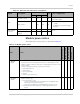
Table 5-5: Power state transitions (including voltage/temperature trigger levels)
Transition
Voltage
Temperature
1
Notes
Trigger
V
2
Trigger °C
Normal to Low Power
VOLT_HI_CRIT 3.8 TEMP_LO_CRIT -45
• RF activity suspended
VOLT_LO_CRIT 2.9 TEMP_HI_CRIT 110
Low Power to Normal VOLT_HI_NORM 3.5 TEMP_NORM_LO -40
• RF activity resumed
Low Power to Normal
or
Remain in Normal
(Remove warnings)
VOLT_LO_NORM 3.05 TEMP_HI_NORM 85
Normal (Issue warning) VOLT_LO_WARN 2.95 TEMP_HI_WARN 95
Power off/on
(Host-initiated)
- - - -
• Power off recommended when
supply voltage or module
operating temperature is critically
low or high.
1. Module-reported temperatures at the printed circuit board.
2. Supply voltage—3.3V