
Specifications


Power
Rev 8 Apr.14 Proprietary and Confidential - Contents subject to change 53
Module power states
The module has four power states, as described in Ta ble 5 - 4.
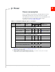
Table 5-3: Miscellaneous DC power consumption
Signal Description
Current/Voltage
Unit Notes/configuration
Min Typ Max
VCC
USB active current 10 15 mA
High speed USB connection, C
L
= 50 pF
on D+ and D- signals
Inrush current 750 2500 mA
• Assumes power supply turn on time
>100µs
• Dependent on host power supply
rise time.
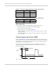
GNSS Signal
connector
Active bias on GNSS port 50 75 100 mA GNSS connector in Figure 4-1 on
page 41
Max. voltage output
@ 75mA
3.3 V
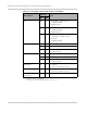
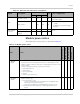
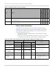
Table 5-4: Module power states
State Details
Host is powered
Module is powered
USB interface active
RF enabled
Normal
(Default
state)
• Module is active
• Default state when VCC is first applied in the absence of W_DISABLE_N control
• Module is capable of placing/receiving calls, or establishing data connections on the
wireless network
• Current consumption is affected by several factors, including:
• Radio band being used
• Transmit power
• Receive gain settings
• Data rate
• Number of active Tx time slots
Low power
(‘Airplane
mode’)
• Module is active
• Module enters this state:
• Under host interface control:
· Host issues AT+CFUN=0 ([1] AT Command Set for User Equipment (UE)
(Release 6) (Doc# 3GPP TS 27.007)
)), or
· Host asserts W_DISABLE_N, after AT!PCOFFEN=0 has been issued.
• Automatically, when critical temperature or voltage trigger limits have been
reached