
Specifications


Rev 8 Apr.14 Proprietary and Confidential - Contents subject to change 51
5
5: Power
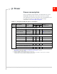
Power consumption
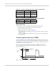
Power consumption measurements in the tables below are for the
MC7304 Mini Card module connected to the host PC via USB.
The module does not have its own power source and depends on the
host device for power. For a description of input voltage
requirements, see Power supply on page 30.
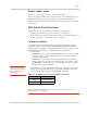
Table 5-1: Averaged standby DC power consumption
Signal Description
Bands
1
Current
Notes /
configuration
Typ
Max
2
Unit
VCC Standby current consumption (Sleep mode activated
3
)
LTE LTE Bands 1.8 3.0 mA DRX cycle = 8 (2.56 s)
HSDPA / WCDMA UMTS bands 1.8 3.0 mA DRX cycle = 8 (2.56 s)
GSM / GPRS / EDGE GSM bands 2.4 3.5 mA MFRM = 5 (1.175 s)
Standby current consumption
4
(Sleep mode deactivated
3
)
LTE LTE bands 25 30 mA DRX cycle = 8 (2.56 s)
HSDPA / WCDMA UMTS bands 23 28 mA DRX cycle = 8 (2.56 s)
GSM / GPRS / EDGE GSM bands 27 32 mA MFRM = 5 (1.175 s)
Low Power Mode (LPM)/Offline Mode
4
(Sleep mode activated
3
)
RF disabled, but module is operational 1.3 1.6 mA
Low Power Mode (LPM)/Offline Mode
4
(Sleep mode deactivated
3
)
RF disabled, but module is operational 23 27 mA
1. For supported bands, see Table 4-1, LTE frequency band support, on page 46, Table 4-3, WCDMA frequency
band support, on page 46, and Table 4-4, GSM frequency band support, on page 47.
2. Measured at 30ºC/nominal voltage.
3. Assumes USB bus is fully suspended during measurements
4. LPM and standby power consumption will increase when LEDs are enabled. To reduce power consumption,
configure LEDs to remain off while in standby and LPM modes.