
Specifications

Rev 8 Apr.14 Proprietary and Confidential - Contents subject to change 41
4
4: RF Specifications
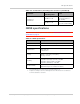
The MC7304 includes three RF connectors for use with host-supplied
antennas:
• Main RF connector—Rx/Tx path
• GNSS connector 1—Dedicated GNSS
• Diversity/MIMO connector—Diversity or MIMO
The module does not have integrated antennas.
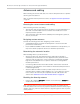
Figure 4-1: Module connectors
RF connections
When attaching antennas to the module:
Note: To disconnect the
antenna, make sure you
use the Hirose U.FL
connector removal tool
(P/N UFL-LP-N-2(01)) to
prevent damage to the
module or coaxial cable
assembly.
• Use Hirose U.FL connectors (3 mm x 3 mm, low profile; model
U.FL #CL331-0471-0-10) to attach antennas to connection points
on the module, as shown in Figure 4-1 on page 41.
• Match coaxial connections between the module and the antenna
to 50 .
• Minimize RF cable losses to the antenna; the recommended
maximum cable loss for antenna cabling is 0.5 dB.
• To ensure best thermal performance, mounting holes must be
used to attach (ground) the device to the main PCB ground or a
metal chassis.
Note: If the antenna connection is shorted or open, the modem will not
sustain permanent damage.
Shielding
The module is fully shielded to protect against EMI and must not be
removed.
I/O connector
Main RF connector
GNSS connector
Diversity / MIMO