
Specifications

Product Technical Specification & Customer Design Guidelines
36 Proprietary and Confidential - Contents subject to change 4114634
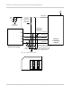
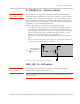
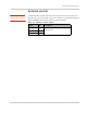
Figure 3-7: Example LED
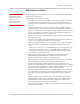
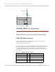
SYSTEM_RESET_N—Reset Input
Note: SYSTEM_RESET_N signal support is optional.
SYSTEM_RESET_N has an internal 1.8 V internal pull up. Set this signal to
active low to reset the device. Note that the minimum pulse width is 250 ms.
PCM/I2S Audio Interface
Note: PCM Master/Slave mode, Auxiliary PCM mode, and I2S Master modes are
supported; I2S Slave mode is not supported.
The default setting is PCM slave mode.
The module implements a PCM/I2S digital audio interface using a dedicated
serial link for digital audio data; all other signals, such as subcoding and control,
are transmitted separately. The audio interface could be switchable via AT
command between PCM and I2S. The PCM/I2S signals are summarized in the
following table.
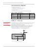
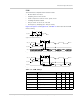
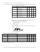
Table 3-6: PCM/I2S Interface signals
Signal name Pin Description
PCM_CLK/I2S_CLK 45 PCM Clock/I2S Clock
PCM_DOUT/I2S_DOUT 47 PCM Data Out/I2S Data Out
PCM_DIN/I2S_DIN 49 PCM Data In/I2S Data In
PCM_SYNC/I2S_WS 51 PCM SYNC/I2S WS
Current limiting Resistor
LED
VCC
MIO
MiniCard
WAN_LED_N