
Specifications
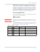

Electrical Specifications
Rev 8 Apr.14 Proprietary and Confidential - Contents subject to change 35
W_DISABLE_N — Wireless disable
Note: Wireless disable
signals support is optional.
The host device uses W_DISABLE_N (pin 20) to enable/disable the WWAN or
radio modem. When disabled, the modem cannot transmit or receive information.
Letting this signal float high allows the module to operate normally. This switch
follows the behavior described in [9] PCI Express Mini Card Electromechanical
Specification Revision 1.2. This pin has a 20 k pull-up resistor. See Figure 3-6
on page 35 for a recommended implementation.
When integrating with your host device, keep the following in mind:
• The signal is an input to the module and should be driven LOW only for its
active state (controlling the power state); otherwise it should be floating or
(High impedance). It should never be driven to a logic high level. The module
has an internal pull-up resistor to Module Power (3.3V) in place, so if the
signal is floating or (high impedance), then the radio is on.
• Wait for two seconds after asserting W_DISABLE_N before disconnecting
power.
• If the host never needs to assert this power state control to the module, leave
this signal unconnected from the host interface.
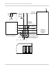
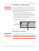
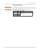
Figure 3-6: Recommended wireless disable connection
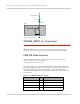
WAN_LED_N—LED output
Note: WAN_LED_N signal
support is optional.
The module drives the LED output according to [9] PCI Express Mini Card
Electromechanical Specification Revision 1.2.
Note: The LED configuration is customizable. Contact your Sierra Wireless account repre-
sentative for details.
MiniCard
R
Wireless disable control
(W_DISABLE_N)
1
2
3
Q
20k
Host
VCC